Motorola CPS on Windows 10/11

It is no secret that Motorola CPS software does not like to run on modern operating systems. I still have a number of UHF Motorola MTS2000 handhelds which once given new batteries have proven themselves useful time and time again.

However my trusty old Windows XP laptop, with a real serial port fried its motherboard recently never to boot again. My immediate thought was “yikes what do I use now to program these Motorola radios” ?

So rather than go looking for further ancient hardware I started experimenting if Motorola CPS would run on a Windows 10 64-bit platform. I’ll spare you the gory details, but not amount of compatibility mode twiddling or research would result in a working system. There is something fundamental in the RS232 32-bit sub-system within the CPS software that prevents this from ever working. I could not get the CPS software to “read device” instead receiving a timeout. Grrrr….

So the only alternative was to experiment with an older version of Windows in a virtual machine and passing through a serial port. I remember when Windows 7 was first released Microsoft released a version of Windows XP that would run within Microsoft Virtual PC. The Motorola CPS software is from around the same time, so it was an ideal candidate to try. Turns out this was easier than I expected.

Setup Windows XP Virtual Machine

I found the following setup guide very useful from Help Desk Geek website (click). The download link from the Microsoft site has disappeared, but the alternative link from the CNET site was working at the time of this post.

I followed this guide closely, there are a few steps you needed to pay attention too but otherwise this went smoothly. I’m currently using a Windows 10 host and the only trouble I had was with the mouse, where I could not control the mouse within the Guest correctly, but you can temporarily disable the VirtualBox “mouse integration” feature to get around this until the VirtualBox Guest Additions are installed. Once the Guest additions were installed, everything worked as expected.

Activating Windows XP in 2022

The next challenge is since Windows XP support ended there is no way to “activate” this vanilla of windows any more which is right painful. One work around is to snapshot the VM and rollback each time you wish to use it, I wasn’t a fan. So thankfully the “Adventures in Nostalgia” YouTube channel had a video that shows how a regedit method to work around this problem, don’t forget to leave a like.

Serial Port Pass Through

Now I’m lucky that my Gen-3 I7 desktop machine has a real serial port on the motherboard. This was one of the very last Intel made motherboards with the legacy IO chipset, so not only do I have a serial port it has a parallel port too.

To allow Windows XP access to the host serial port, one just needs to configure the hardware pass through. Within the VirtualBox settings there is a separate “Serial Port” tab that simply requires mapping between the guest and host systems.

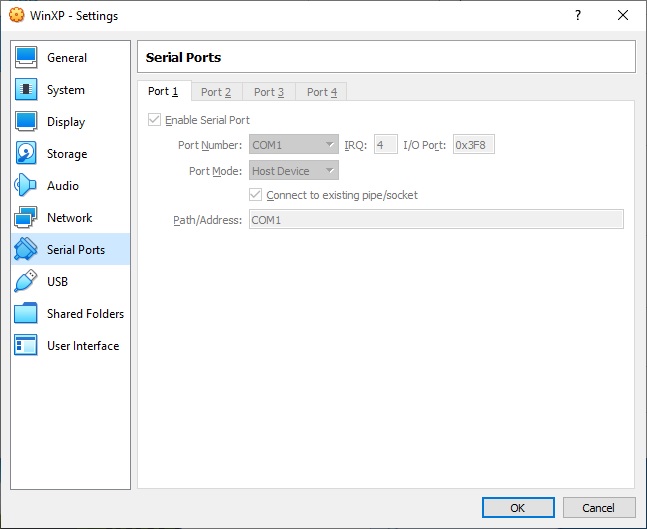
As you can see I’ve simply mapped COM1 on the guest to COM1 on the host, simples !

Copying Motorola CPS into Windows XP

So for the grand finale we can install the Motorola CPS software within Windows XP. How one gets the software installed can be done a few different ways.

I decided to use the VirtualBox shared folders mechanism. With the guest additions installed I found once I’d configured the shared folders they were automatically mapped as a network drive the next time I restarted the Windows XP guest. It was a simple matter to then double click the executable and install.

There were a few websites with rough instructions, but I found after watching the following YouTube video from Peter Downie I was able to get it working in short order;

The other method I’ve used to pass software through to a guest is to use a USB thumb drive. Copy the files from the host to the USB, pass the USB through to the guest, move the files and eject to pass it back. Both methods work just as well as each other.

The Proof is in the Pudding

So once you can copy the relevant files into the VM, then it’s a simple matter to install and run the Motorola CPS software. Then simply configure it to talk to the serial port you’ve passed through which is COM1 in my case, then try to read a physical radio. Please note that Motorola CPS software is licensed and cost real $$$ to purchase, please do not request copies of said software fro me as refusal often offends.

You will know you’ve got it right when you hear the radio beep, it says PRGM on the radio display and you are greeted with the contents of your code plug.

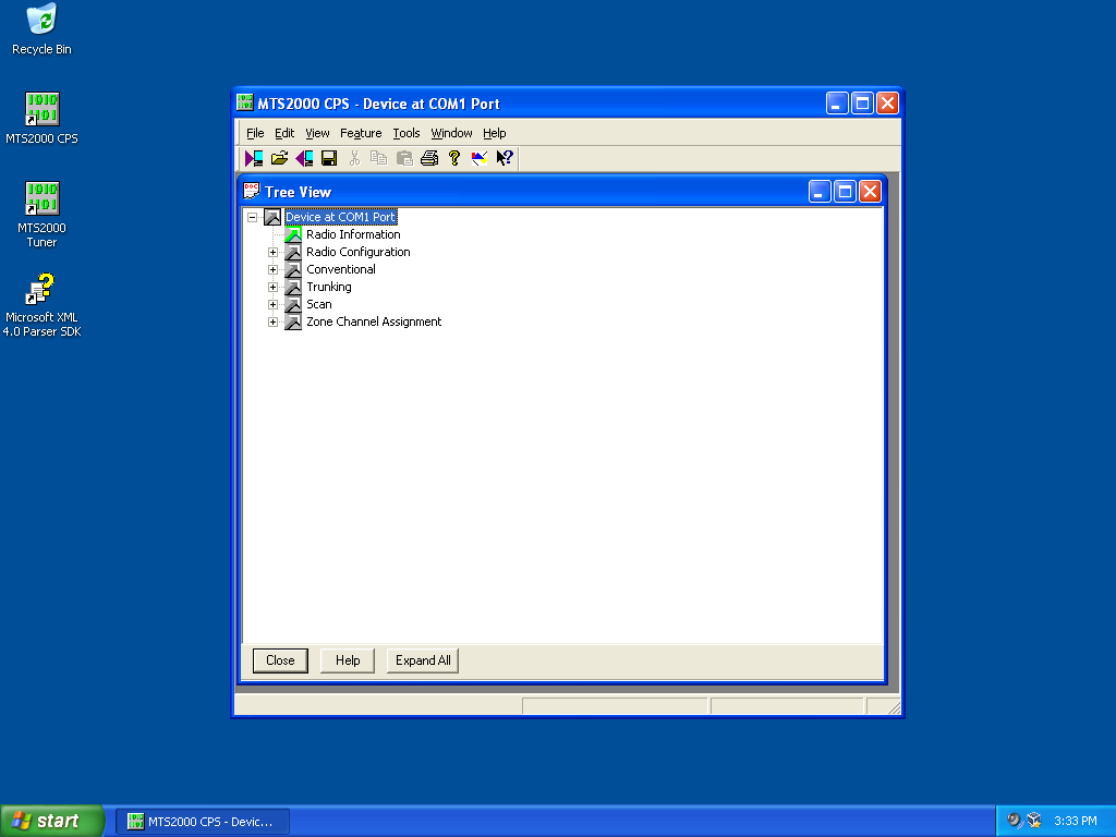
I was certainly relieved to be greeted with the screen shown above, make my changes and write the config back to the radio. I’m once again in business. I hope that other users of older Motorola CPS software find this useful.

How do you get on 23cm ?!?

I was recently looking at getting some radio gear that would get me up onto the Australian 23cm Amateur Radio Band. My first thoughts was to find some second hand commercial amateur gear, but this was soon dashed when 20 year old radios on eBay were fetching more than A$1000 in less than pristine condition. They are hard to find !

My second thought was of course a transverter. Where I would take one of my 2m or 70cm transceivers and “up-convert” the output onto the 23cm band. This is usually done by a combination of loads, mixers, fixed oscillators and amplifiers that you buy assembled or as a kit. Since I wanted to do both FM and SSB this presented something of a problem as the receive transmit frequency split for Australian 23cm repeaters is +20MHz. This means the radio attached to the transverter IF port has to be capable of wide band receive, which is not very common. So my calculator again suggested after I’d built a transverter, added a dedicated IF radio I’d be somewhere northwards of A$750… sigh that second hand commercial radio looked good again.

One of my local radio club members then introduced me to the Analog devices ADALM-Pluto SDR and the Pluto Charon 23cm module from Minikits here in Adelaide. I was hooked and two new toys were duly ordered and shipped. The cost of both the ADALM Pluto and Charon 23cm module was less than A$450 delivered but I did have to do a little shopping around to get the Pluto at a good price.

I then started researching what exactly you can do with one of these little devices and what exactly I’d just bought. I’m simply amazed at what Analog Devices have stuffed into this little box, better yet I’d received one of the Rev D platforms which has all the bells and whistles. As I discover things about the Pluto, I’m sure to blog them here soon.

I was again pleased to find the ADALM-Pluto was already supported by SDR-Console written by Simon Brown G4ELI. I’ve used SDR Console for many years in all of my HF contesting stations to display waterfall information. Using it for transmit was going to be a new experience.

Now to wait for that postman !

Display a PNG Image on small 128×128 OLED LCD

Now that my small OLED display automatically loads the device drivers on boot, it was time to see if I could display an image on my new frame buffer device.

To start with I went looking for a very basic graphics library that would allow me to experiment on frame buffer devices. There is certainly no shortage of libraries to choose from. The library that I settled on was the “Lightweight C 2D graphics API agnostic library with parallelism support” written by grz0zrg. It had both PNG and JPG routines that could output to a simple frame buffer device, being written in C was also a winner.

Flicking through the various examples the quickstart.c file seemed to have nearly everything I needed to display a PNG file on my OLED. Not so long ago a fellow AREG club member shot me some icon files for our club website; one of these icons was 512×512 pixels in size which made it an excellent candidate for shrinking to 128×128 pixels and using it on my OLED.

Downloading the library was as easy as;

$ cd ~
$ git clone https://github.com/grz0zrg/fbg

If you don’t have git installed use the relevant apt-get command. The example files can then be found in the following directory;

$ cd ~/fbg/examples 

I then copied the quickstart.c file and hacked on it a little, modifying it like so;

#include <sys/stat.h>
#include <stdio.h>
#include <signal.h>
#include "fbgraphics.h"

int file_exists( const char* filename )
{
    //define file handle
    FILE *file;

    //attempt to open file read only
    if( (file = fopen(filename, "r")) )
    {
        fclose(file);    // release file handle
        return 1;        // tell someone we found it
    }
    else
    {
        return 0;         //no one home
    }
}

int main(int argc, char* argv[])
{
    const char* framebuffer_name = "/dev/fb1";
    const char* logo_filename = "logo.png";

    //check we have a framebuffer to talk to
    struct _fbg *fbg = fbg_setup( (char *)framebuffer_name, 0);
    if (fbg == NULL)
    {
        return -1;
    }

    // make sure logo file exists
    if( !file_exists( logo_filename ))
    {
        printf("File not found: %s\r\n",logo_filename);
        return -2;
    }

    //draw something on the display
    struct _fbg_img *logo = fbg_loadPNG(fbg, "logo.png");
    fbg_clear(fbg, 0);
    fbg_image(fbg, logo, 0, 0);
    fbg_flip(fbg);
    fbg_draw(fbg);

    //release memory
    fbg_freeImage(logo);
    fbg_close(fbg);

    return 0;
}

Which was built with the following command line from within the examples directory;

gcc ../src/lodepng/lodepng.c ../src/nanojpeg/nanojpeg.c ../src/fbgraphics.c display_logo.c -I ../src/ -I. -std=c11 -pedantic -D_GNU_SOURCE -D_POSIX_SOURCE -Wno-unused-value -Wno-unknown-pragmas -O2 -Wall -lm -o display_logo

Hacking upon the Makefile is also not that difficult, I simply added the relevant lines the SRC and OUT sections, then copied the quickstart section and renamed display_logo. There is lots of information about on how to do this on the internet so I’ll not repeat it again unnecessarily.

All I had to do then was place my 128×128 PNG file alongside the display_logo executable (renamed logo.png) and run it… wallah ! I was greeted by the AREG logo on my small OLED display in all of its 128×128 pixel glory; see the image at the top of this post.

So the next trick is to move this to the boot process… So by the looks the plymouth package might be the go, only one way to find out.

Starting a fbtft_device on Boot

After having woken up my small 128×128 OLED display I was wondering how to get it to start automatically each time my rPi booted rather than having to log in and run the commands manually.

It turns out this is rather easy and just required me to edit two files. I’m also glad that these Waveshare OLED displays are effectively compatible with the Freetronics OLED 128×128 graphics display. A big thanks to the Freetronics team for making this driver available for SED1351 chip sets.

So I created the following file with my favourite editor (as root) /etc/modprobe.d/fbtft.conf with the following contents;

options fbtft_device name=freetronicsoled128

What this effectively does is tell the system how to configure the fbtft_device as it boots, much like if we started it with modprobe from the command line i.e used the following command;

sudo modprobe fbtft_device name=freetronicsoled128

So now the system knows how to configure the driver, we need to tell modprobe to load it by placing an entry in the /etc/modules file. So using your favourite editor (as root) edit /etc/modprobe and append the last two lines.

# /etc/modules: kernel modules to load at boot time.
#
# This file contains the names of kernel modules that should be loaded
# at boot time, one per line. Lines beginning with "#" are ignored.

i2c-dev
spi-bcm2835
fbtft_device

It appears that the SPI bus is a little slow to load if it’s called as a dependency of fbtft_device, which is a classic chicken and egg driver problem. So by starting it manually we make sure it’s available by the time the fbtft driver tries to do anything.

The i2c-dev entry in the same file fires up the i2c bus and was already pre-configured in my system by raspi-config way back when. I’m using it in my project, YMMV. All that is left to do is test it, so reboot and login and run the following command;

$dmesg | grep graphics

We should see something like the following;

[6.128978] graphics fb1: fb_ssd1351 frame buffer, 128x128, 32 KiB video memory, 4 KiB buffer memory, fps=20, spi0.0 at 20 MHz

That tells us that the little OLED display has registered as /dev/fb1 and that it’s ready to go. You can use the con2fbmap trick in my last post to test it’s working.

Now to work out how to get it to throw up an image on boot…

Small OLED Display on a rPi

Recently I was searching for a small graphic display that I could connect to a Raspberry Pi and fit within a Phoenix DIN enclosure I wanted to use.

There isn’t much space in the front of the enclosure I wanted to use, but a small 128×128 OLED colour display seemed it might fit.

Trawling through eBay I found what I thought to be a suitable unit and simply placed an order. There was very little information on the eBay site to tell me which display I had purchased so I just waited. When the display arrived it turned out to be a Waveshare SKU:14747 with the SED1351 controller.

A little searching around the web and I found an excellent tutorial written by the Freetronics Team for their 128×128 OLED display. It turns out our displays share the same SED1351 controller, so it was the logical place to start with my small display.

First task was to map the OLED pins to my rPi 3B+ 40-pin GPIO connector. On the rear of the display the pins and their desired function were clearly marked, so I mapped the pins like so;

OLED    | rPi      (pin)
--------+----------------
+5      | 5V       (1)
GND     | 0V       (3)
MOSI    | SPI_MOSI (19)
SCK     | SPI_SCK  (23)
CS      | SPI_CE0  (24)
DC      | GPIO25   (22)
RST     | GPIO24   (18)

I have also included the rPi pin numbers I used, make sure you plug the display into the right pins if in doubt RTFM. Once it was wired I ran the following commands to make sure the rPi was absolutely up to date;

sudo apt-get update
sudo apt-get dist-upgrade
sudo reboot

The latest version of Raspbian Lite I was using (Buster) came with the fbtft frame buffer drivers already installed, so these steps were unnecessary. Since this Raspbian installation was fairly recent I decided that I didn’t need to update the rPi firmware using the rpi-update command like in other tutorials; YMMV.

I had already enabled the SPI bus on my Pi when I was coming to grips with the I2C bus. I found the tutorial at Sparkfun a really good reference and easy to follow. To create the frame buffer for the OLED device I ran the following command;

sudo modprove fbtft_device name=freetronicsoled128
dmesg | tail -20

Fingers crossed we see the following output in our terminal;

fbtft: module is from the staging directory, the quality is unknown, you have been warned.
fbtft_device: module is from the staging directory, the quality is unknown, you have been warned.
spidev spi0.0: spidev spi0.0 125000kHz 8 bits mode=0x00
spidev spi0.1: spidev spi0.1 125000kHz 8 bits mode=0x00
bcm2708_fb soc:fb: soc:fb id=-1 pdata? no
spidev spi0.0: Deleting spi0.0
fbtft_device: GPIOS used by 'freetronicsoled128':
fbtft_device: 'reset' = GPIO24
fbtft_device: 'dc' = GPIO25
spidev spi0.1: spidev spi0.1 125000kHz 8 bits mode=0x00
spi spi0.0: fb_ssd1351 spi0.0 20000kHz 8 bits mode=0x00
fb_ssd1351: module is from the staging directory, the quality is unknown, you have been warned.
graphics fb1: fb_ssd1351 frame buffer, 128x128, 32 KiB video memory, 4 KiB buffer memory, fps=20, spi0.0 at 20 MHz

The output here shows us that the SPI bus is OK and that we now have a frame buffer /dev/fb1 that is expecting to find a SED1351 LCD controller. So now it was time to display something so I used following command;

con2fbmap 1 1

And here is what I see;

w00t it works ! Now it’s time to go and find some graphics libraries that can talk to this frame buffer device… and to work out how to display text in boxes that is wider than 80 columns in WordPress…

MQTT Paho C Library

One of my upcoming “Radio” projects involves MQTT running on a raspberry Pi. I’m more familiar with C than I am with Python so to talk to the MQTT broker I went looking for a C based client.

I eventually settled on the Eclipse Paho MQTT C Client library, however it doesn’t come with an ARM based Linux binary package like you get for all the python peeps. Instead you’ve got to compile this from source, I guess since I’m intending to use C in the first place I should be OK. So back to the command line.

Starting with a bone stock installation of Raspbian Buster Lite I simply used the following commands in a shell;

$ sudo apt-get install git libssl-dev doxygen graphviz
$ cd /tmp
$ git clone https://github.com/eclipse/paho.mqtt.c
$ cd paho.mqtt.c/
$ make
$ make html 
$ sudo make install
$ cd /tmp
$ rm -rf paho.mqtt.c

I found all of the commands above in the git repository README.md file. One thing I noticed was when compiling the libssl-dev library generated a good many “deprecated” warnings about old TLS ciphers being used (ie TLS 1.1, 1.2, 1.3 and SSL 2.0 & 3.0) so if you’re intending to use these it might be best to dig a little further. In my case this wasn’t important so I’ve filed it away here as a note to self for future reference.

So now it was just a question if the library works, the simplest way to do this was to compile the included examples and see if they work. So back off to the command line we go.

Eclipse Mosquitto on a rPi

For a while now I’ve been meaning to investigate the Message Queuing Telemetry Transport protocol or MQTT as it’s more commonly known. While the protocol is nearly 20 years old it has become increasingly popular with the Internet of Things (IoT).

The original MQTT code was donated by IBM and Eurotech to the Eclipse Paho project more than 10 years ago now and since then has been extended and massaged into what is known as Mosquitto today. I also like that Eclipse have done a lot of work writing clients for a great many platforms making the developers job just that much easier. A few of my friends have used it professionally so it comes recommended and seems like a good place to start.

So I wanted to experiment with this on a Raspberry Pi (there is a plan more on this later!), so after a bit of googling I found a nice guide written by Adafruit (click) that was the basis of what I used to setup my MQTT stack.

The following is what I needed to do to install Mosquitto on a stock installation of Raspbian Buster Lite. The Mosquitto package is available pre-compiled for ARM in the Debian repo’s so that makes life much easier;

$ sudo apt-get install mosquitto mosquitto-clients
$ cd /etc/mosquitto/conf.d/
$ pico mosquitto.conf

Once pico has created thew mosquitto.conf file then copy the following configuration into it;

# Config file for mosquitto
#
# See mosquitto.conf(5) for more information.

user mosquitto
max_queued_messages 200
message_size_limit 0
allow_zero_length_clientid true
allow_duplicate_messages false

listener 1883
autosave_interval 900
autosave_on_changes false
persistence true
persistence_file mosquitto.db
allow_anonymous true
password_file /etc/mosquitto/passwd

The configuration above is just a basic one for testing. It is by no means secure or ready for production systems, you have been warned. Once the config has been written the following two commands can be used to start Mosquitto and check it is actually running;

$ sudo systemctl start mosquitto.service
$ sudo systemctl status mosquitto.service 

There are small apps that can be used to throw data into the MQTT broker and create topics to publish and subscribe data to and from. Once I’ve worked this out for myself I’ll throw something here.

Rubidium Reference – BITE

The Efratom LPRO-101 has a Built in Test Equipment (BITE) signal available on Pin 6. This pin is connected to the 5V logic within the module. When the BITE signal goes LOW (0V) then the physics engine has achieved lock within roughly +/-5×10-8 of it’s absolute frequency. Thankfully it can do this within 3-4 minutes of operation.

When I’m out in the field it is certainly useful to know what the reference is doing or if something has gone wrong without having to pull it apart and get out a multimeter. So on the front panel I’ve placed two LEDs one for power and the second to show lock.

The lock signal will be nothing more than the BITE signal inverted, which can be done with one transistor. I’ve seen some quite elaborate two and three transistor circuits, but we only really need one. The circuit I’ve draw below is straight out of my engineering log book, it’s so simple I couldn’t be bothered firing up Altium to draw it;

Basically we use one transistor to shunt the LED so that it is OFF while the BITE signal is HIGH. There is no rocket science here. With the heaters in the reference drawing 1.2A at startup throwing an additional 15mA through a transistor until it’s locked should be no big deal. The entire current drawn is approx 30mA, they are certainly bright enough in daylight, they might require turning down after using this at night, time will tell.

The circuit above is so simple I built it dead bug style on a piece of vero board. I did this so I could simply use double sided tape to hold it to the box and not short anything out.

One minor annoyance I’ve found is at the time power is applied the BITE output remains LOW for half a second or more before it goes HIGH. This means that the locked LED will light momentarily, then go out for 3-4 minutes as the reference warms before it lights again. The video below shows what I mean, for such a simple circuit I’m happy to put up with this feature;

You can hear the first click of the power supply, the Locked LED will light and go back out again. This was done when the reference was already warm so it takes less than 20s to regain lock again.

Anyway I’m certainly pleased with the simplicity. However now I’ve got ideas to use a micro a DAC and give this thing some intelligence. More notes in the log book for when I find time to come back to this again, for now it’s time to get out in the field and use it in anger !

Posted in EME

Rubidium Reference – The Retest

It can take a GPS disciplined oscillator a while to stabilise and settle down. When I first tested my new free running rubidium reference the GPS disciplined rubidium reference had spent no more than an hour making it’s observations and corrections. So I left it running over night with the intention of measuring things again in the morning.

So after 16 hours the frequency error has reduced more than three decades, should be good to go. I also have a precision TXCO reference (SDI FEL-10A) so I thought I’d measure this first and see what sort of stability and accuracy this can achieve. Both the free running TXCO and Rubidium were switched on 30 minutes and left to stabilise before measurements were made;

So that is quite a respectable result, being within +0.318Hz of our 10MHz target. Then for the main event it was time to re-measure the free running rubidium;

So this is a little higher that what was measured last night, but +0.009Hz or +9mHz is still a great result. To put this into perspective if I were to use this reference to lock a series of transverters this is the final frequency accuracy I would expect;

F(carrier) | F(error)
[MHz] | [Hz]
-----------+-----------
50.195 | +0.45Hz
144.135 | +1.30Hz
432.070 | +3.88Hz
1296.070 | +11.66Hz

I think if I were to go higher than 70cm then a GPS disciplined oscillator is in order (there is a Trimble Thunderbolt in a box somewhere), at least I have some idea now what the upper workable limit is. One of these days I may yet get in and tweak the external C-Field input and see if I can tighten this frequency error up a little, that will have to wait for a 12-digit counter.

The free running TXCO also has a reference input so for a laugh I attached the free running Rubidium to the TXCO and waited to see what happened. The lock LED lit pretty much instantaneously and the result was;

Exactly the same as the Rubidium on it’s own. What I do like about the TXCO is the 6 channel output with >120dB of isolation between channels. At least now I have some idea how stable this oscillator is, so now I can start thinking about what I’ll do with it.

Posted in EME

Rubidium Reference – Final Tests

Now the million dollar question is does it work ? Testing one of these rubidium references means you need a reference and counter that’s more accurate that the reference you’re trying to measure.

Fortunately one of my club members has a GPS disciplined Rubidium Oscillator that can attain some silly levels of stability and accuracy. Giving this device a few hours to watch satellites and let it discipline the internal oscillator is enough to then make some very accurate measurements. Even in the first 16 minutes this oscillator is able to achieve a frequency error less than what we need to make our measurements, after a further hour this number decreases yet another decade.

Once you have the uber accurate reference and accuracy you still need a counter with enough digits. This turns out to be something of a problem, all of the frequency counters I can find seem to stop at 8 digits. Which means you can only measure to the nearest hertz.

At work we have been cleaning up more than 25 years of Engineering mess and while we were cleaning we found a HP 5385A frequency counter stashed in a cupboard that no one knew was there, this particular counter can accept an external 10MHz reference. Combine this with a gate time of 10s it’s able to extend it’s display to a full 11 digits, meaning we can see down to the nearest milliHertz. So that just had to come home for the weekend to test it was working you see. They are actually reasonably priced on Ebay, so I can see a purchase coming on in the not too distant future.

So the measurement of my free running Rubidium reference is now rather simple. The GPS disciplined Rubidium drives the external reference of the HP 5385A counter, our test rubidium is then attached to the appropriate input. Then we need to give everything a good hour to reach thermal equilibrium and stablise. We can then make our final measurement.

I’ve not yet placed a thermocouple on the heat sink and made any measurements but it is certainly much cooler to the touch then when I ran it with just the enclosure.

So above is all of the test gear spread out on the kitchen table (shhh !) the GPS cable exits out a door so it can see the sky. The multimeter is reading the buffered Lamp Voltage, ideally this should be between 6-9 volts for a healthy Rubidium. Alas this rubidium probably has only a few years life left in it before it has to be refurbished.

However from this distance it’s a bit hard to read the counter, so here’s the closeup;

That is an awful amount of zeros, however it shows that my free running rubidium is running just +5.0 milliHz fast or +5.0×10^-9 Hz in scientific notation. Wow it works !

As you can see I’m now looking for that 12-digit frequency counter so that I can see just how good this rubidium is.

I’ve also read that it’s possible to trim the frequency of the 10MHz oscillator a little using the C-trim input pin (#7).. Hmm I guess that is how the GPS disciplined Rubidium does it !?! So with a multi-turn pot (10-20T) it may be possible to trim the frequency to be better than 1×10^-10 with luck and crossing of eye’s. However from what I’ve observed this may be pushing the limits of the thermal stability of these units and the error of the GPS disciplined oscillator will start to come into play.

Anyway I’m reasonably confident now that this Rubidium 10MHz reference will be able to keep my Elecraft K3 transceiver locked onto the right frequency for any EME experiments even in the dead of night.

Now I’ve just got to get the LEDs on the front panel working correctly and how I’m going to power this unit in the field. With a power supply requirement of 24V @ 0.45A this isn’t insignificant.

Posted in EME