Waverley Amateur Radio Society Powerpole Kit

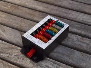
W.A.R.S Powerpole Kit

A few members of the AREG got together and purchased a group buy of the Waverley Amateur Radio Society Powerpole Kits to build.

I got mine for my contesting setup since they were cheap and cheerful and I could screw my West Mountain Radio RigRunner under my bench.

Construction of the units is not difficult and the instructions are nice and clear.   A job well done by the WARS that is for certain.

However with power distribution you’re always wondering just how much current can you run through them without damage.

I’m luck enough to have access to the nice toys at work for testing of power supplies.   So I ran up our grunty PSU on the input, connected the load to output 6 (furthest from input) and ran up a conservative 25A continuous as the worst case and waited.   The majority of my “contesting” radios will reach 25A peak with an average far lower than 25A, should be good enough.   It does mean I’m not too worried if two radios were used at the same time however.

Using a thermographic camera I was then able to go looking for what is “getting hot” a sure sign of something under stress.  After 10 minutes of “thrashing” the temperature stabilised and I was able to capture the following two images.

ir_1367ir_1368

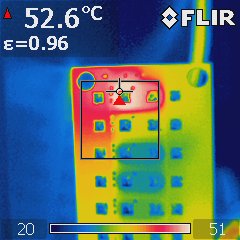
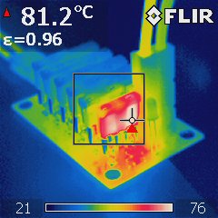
The first image showed me that there was something getting hot at this power level (345W) my initial thoughts were the copper traces or a dodgy solder joint.  It turns out it’s the fuse if you look at the second image.

These automotive blade fuses run stonking hot at high current levels, far hotter than I’d ever considered before in the past.   Keep in mind that these are 30A fuses and were 15% within their rating at the time. This stands to reason when you consider that the fusing capability of such an element is a function of the current (I) squared and time (t).  So the higher the current the shorter the fusing time, the squared term ensures that the relationship is not linear.  The heat from the fuse was far greater than the heat from the traces.

Anyway my rough tests and thermographic images certainly tell me that a properly constructed WARS powerpole kit will happily run within it’s designed ratings of 30A continuous on the input.   Time to order one or two more for the junk box me thinks !

Cruise Control

Just after I’d finished replacing the engine my windscreen wipers decided to call it day.  Driving along a flat piece of road just before dark the wipers and washers decided to come on of their own accord with the switch in the OFF position.

It seems that my intermittent wiper control function had failed short circuit there somewhere, wasn’t hard to yank the connectors off the washer and wipers and carry on back home.  Searching for a new windscreen wiper control module saw my parents standing in a wrecker close to their home fetching me some parts (thanks Mum & Dad!).  Unbeknown to them the wiper and headlight stalk was being pulled out of a petrol automatic 4Runner, which is very close but not quite the same as a Hilux.

Anyway my parents dropped off the newly acquired part and I got my first look at it.  There was one very obvious difference and that was the clock work spring and indicator cancelling mechanisms were different.

Looking closely it took me all of 10 seconds to realise that the clock work spring in this wiper mechanism had switches in the steering wheel, the question was what type; cruise control or radio?

Well that saw my parents back at the Wrecker the following morning to retrieve the attached steering wheel.   I got an excited telephone call to tell me it was the cruise control switches.   Yippee !!!  Had we waited 10 minutes longer we’d have missed out, the second customer through the door of the wrecker that day was after the same steering wheel; Mine, all mine, Shooo !!!

The steering wheel on closer inspection had a loose grip which is unfortunately defect-able (but common) here in South Australia.  So a visit to a local motor trimmer saw the steering wheel repaired.  The best part is the cost of paying someone to repair the wheel was the same as buying a kit to do it myself off eBay; the difference is that I paid someone who knew what they were doing to effect the repair !

The steering wheel and wiper assemblies on 4Runner’s and Hilux’s are readily interchangeable so with a bit of disassembly, un-plugging, re-plugging and re-assembly my Hilux now sports cruise control switches in the steering wheel.  You wouldn’t know it didn’t come without them,.

Searching the net I’ve found a number of after market cruise control systems that are easy to retro-fit to many different vehicles.  All that is required is a speed sensor, clutch switch, tap the brake circuit, plug things together and mount some switches close to the steering wheel.

I’ve got I’ve got a feeling that I can pull a brake switch assembly out of another Hilux and mount this to the clutch pedal for not many $$$.   That would just leave me with mounting a vacuum actuator (some are servo based) and wiring the thing together.   I can see another project in the wind..  At least I have the “factory” steering wheel switches already sorted.

New Switches

With the lights upgraded it was about time I found a decent switch to sit on the dash board and activate the spotties.

I’d noticed recently that Narva offered a series of “Carling” styled switches that came with blue indicators that looked about the right size.  I hate blue lights in cars, it hurts the eyes and causes fatigue.

There are three switch positions in the car that measured up close to a standard 32mm x 26mm DIN cutout.

A bit of google foo and I find online suppliers that can offer the same switch with various printing with a range of indicator colours.  I ordered Green to match the rest of the console.

They fit perfectly.

There was only just a tiny amount of filing required to squeeze the switch into the cutout, perhaps a millimetre or two.   Anyway the effect is great.

The switch has two indicators, the lower that comes on when the lights are activated and a second under the symbol when you activate the switch.   This required a bit of thinking as to how to wire it properly and an additional diode to get it to work with the relay kit.   I should at some stage draw up the circuit diagram.

My only complaint is the LED’s are far brighter than the equivalent incandescent bulb which means even when dimmed by the rheostat they are still too bright.  I’ll be pulling the switch out and wiring a separate resistor in series to lower the brightness further.  Hmm… that might require a transistor and zener, time to get that piece of paper out.

Oh and while I was ordering one “spot lights” switch I grabbed a few others that I thought I might want so there is now a small collection ready and waiting for further improvements.