For the past couple of weeks I’ve been giving some thought as to how I’d box up the Mini-kits Pluto Charon. As with any problem the first step it to work out how I want to use it.
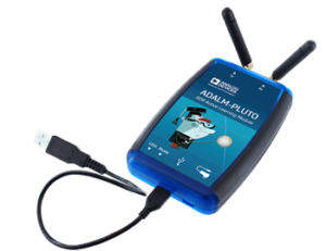
I’d like to be able to use the Pluto Charon both in the field and in the ham shack. The ADLAM Pluto connects to a PC via a micro USB and presents itself as a USB Ethernet device.
Further reading suggests that the ADLAM Pluto USB OTG port can host an external USB-Ethernet adapter or USB-WiFi adapter, making it possible to un-tether the Pluto from a PC or use standard IT infrastructure. In my situation an external Ethernet port is of interest, since I could easily build all of the Mini-Kits Pluto boards into their own enclosure and simply network them together and into the same PC without having to count on multiple USB ports. This again fits with my field and shack mode of operation.
The output power of the Mini-kits Pluto Charon, Pluto Styx and proposed Pluto Nix kit is in the region of one to two watts. This is more than enough transmit power to jump from hilltop to hilltop over quite a path with some antenna gain and short cables. If however you want to lift the antennas up to the top of mast, external in-line amplifiers up behind the antennas would be required to keep losses under control. If the external amplifiers also included a separate mast head amplifier, then losses of up to 6-8dB at any of these microwave frequencies could be accommodated without significantly impacting performance. I’ll be exploring this further once the first Pluto Charon kit is completed.
So, the first step of course is to get the Pluto Charon kit operational, to do that I needed to test it. The kit came with a small 40x40mm heatsink that I could attach to dissipate the heat from the final amplifier IC1. I mulled this over for a while before deciding I’d prefer to put a much larger heatsink on the top of a die cast box and mount the Pluto Charon to that. A good example of what I’m thinking is how I built my Rubidium reference (here). My main reasoning is I’d like to stabilise the heat within the die cast box so the Pluto does not need to work so hard on keeping the frequency stable. Did I mention the Rubidium reference, one would say this started these shenanigans.
To get the heat out of the Pluto Charon final amplifier the layout dictated a small copper block to be made. There are components on the top and bottom of this board, so one needs to pay attention to clearances etc. So it was off to see a good friend with a lathe ;thanks Peter it was a fun afternoon and some good machining Zen !
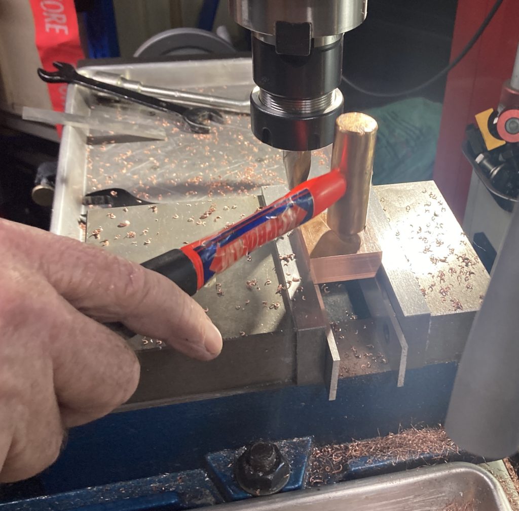
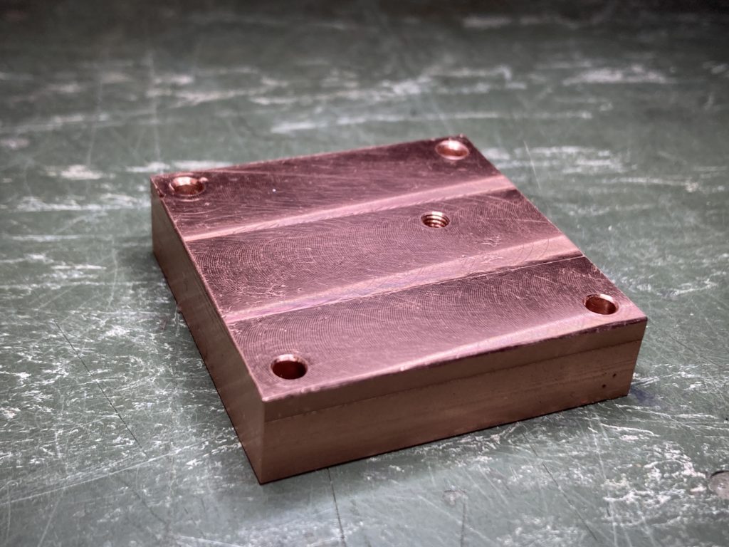
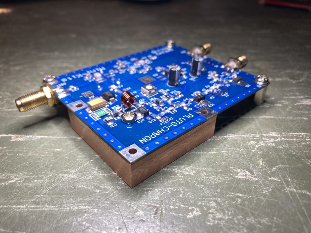
It is no coincidence that the copper block is 10mm thick, this is perfect for three 10mm hexagonal spacers to be placed under the remaining three sides of the PCB for support.
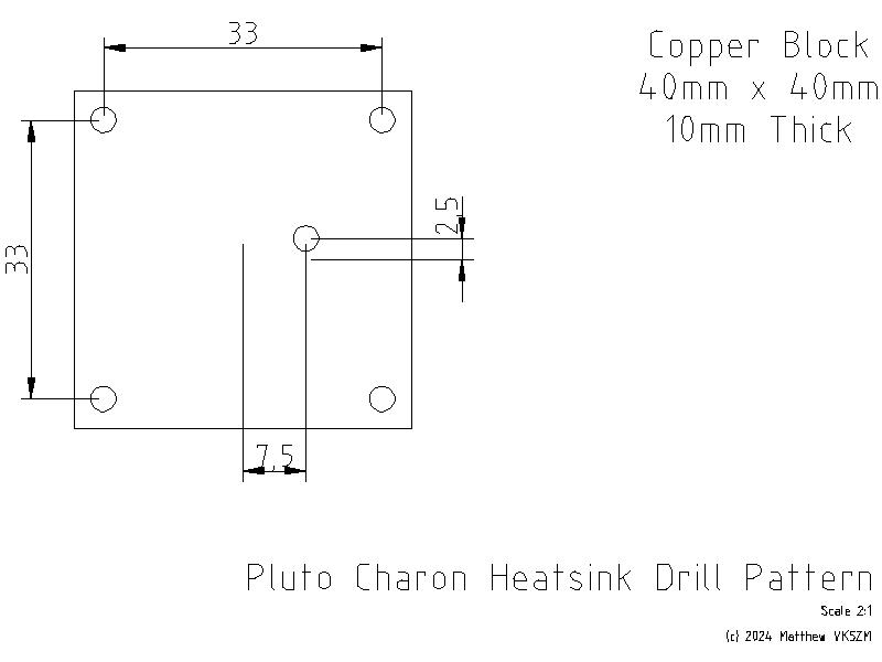
The hole in the middle of the copper block is what transfers the heat from IC1, so this was tapped to accept a M3 hole. The PCB had a plated 2.5mm hole and was reamed out slightly to accept the larger M3 screw. The M3 screw used was tin plated copper, not tin plated steel/stainless which is a poor conductor of heat.
The remaining four holes in the PCB that hold the heatsink were left M2.5 and the holes through the copper block drilled 3mm for clearance. When this is attached to the heatsink, four M2.5 x16mm screws through these holes in the heatsink, washers and split washers will be used to sandwich the assembly and keep everything held tight.
So I don’t forget and for anyone following along at home I’ve included the drill pattern. This was the only information conspicuously absent from the assembly instructions. This drawing is drawn from the top of the PCB looking down. The hole in the middle of the heatsink is referenced from the center of the copper block. For some reason I can’t get LibreCAD to show a mark for the origin yet. I hate having to measure PCB’s to get hole locations, a combination of transfer punches, vernier calipers and gauge pins were used to establish and check that these locations were close enough.
Now it’s time to carry on with the Testing and Alignment of the Pluto Charon !
