In a recent post I wrote about experiments with a Pine A64 running the Project Horus 4FSK binary and Wenet decoders. The next steps were to work out exactly I was going to build.
Systems Diagram
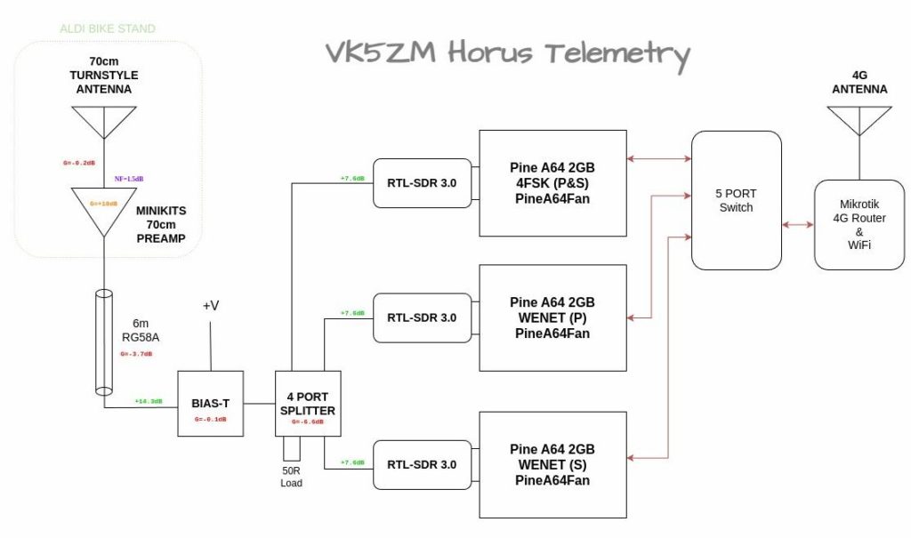
Designing systems is an iterative process, you start with an idea and then modify and adapt as pieces are found and problems are solved. From the outset I wanted to build a HAB Telemetry system that could track the majority of telemetry that the Project Horus Balloon flew, this being the primary and secondary 4FSK binary telemetry and Wenet. There are times when primary and secondary Wenet systems are also flown, so allowances for two Wenet decoders were made.
I wanted this system in a box, that I could take out of the car, place on a table, switch on and magically decode the telemetry from the Balloon. Having everything setup, configured and running, before going into the field, means that less time is lost debugging faulty cables, forgetting where and how to plug things together or worse still chasing down rogue software updates.
A picture speaks a thousand words, so below is a block diagram of what I proposed to build, that would suit my needs above. This was a culmination of the equipment I found rummaging around in my shed, rediscovering more treasures and realising I had only two Pine A64’s and needed three.
Design Evolution
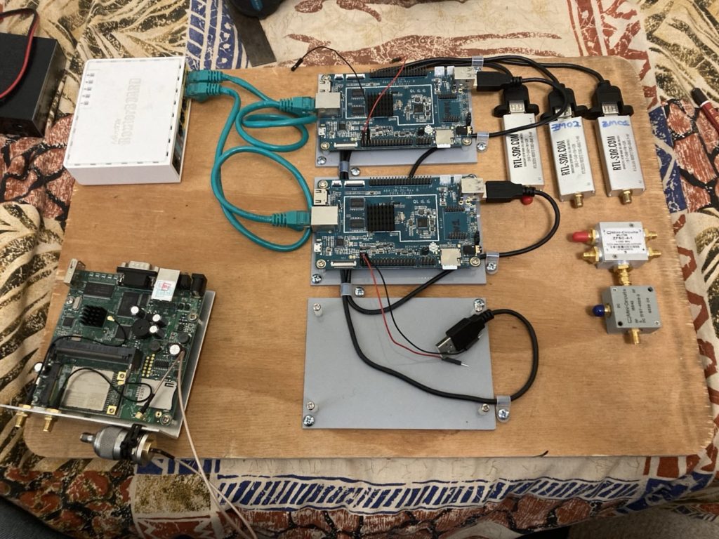
The first “prototype” system was thrown together for the Horus 58 flight, which consisted of the two Pine A64’s I had, some RTL-SDR’s and some Mikrotik routers to get the data out and onto the internet. Here you can see some “design for but not with”, where I’ve left a space for a third Pine A64 that I was yet to find.
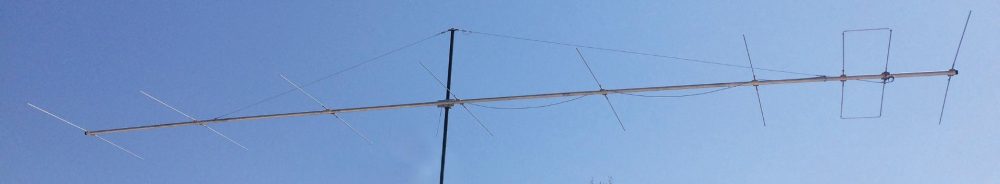
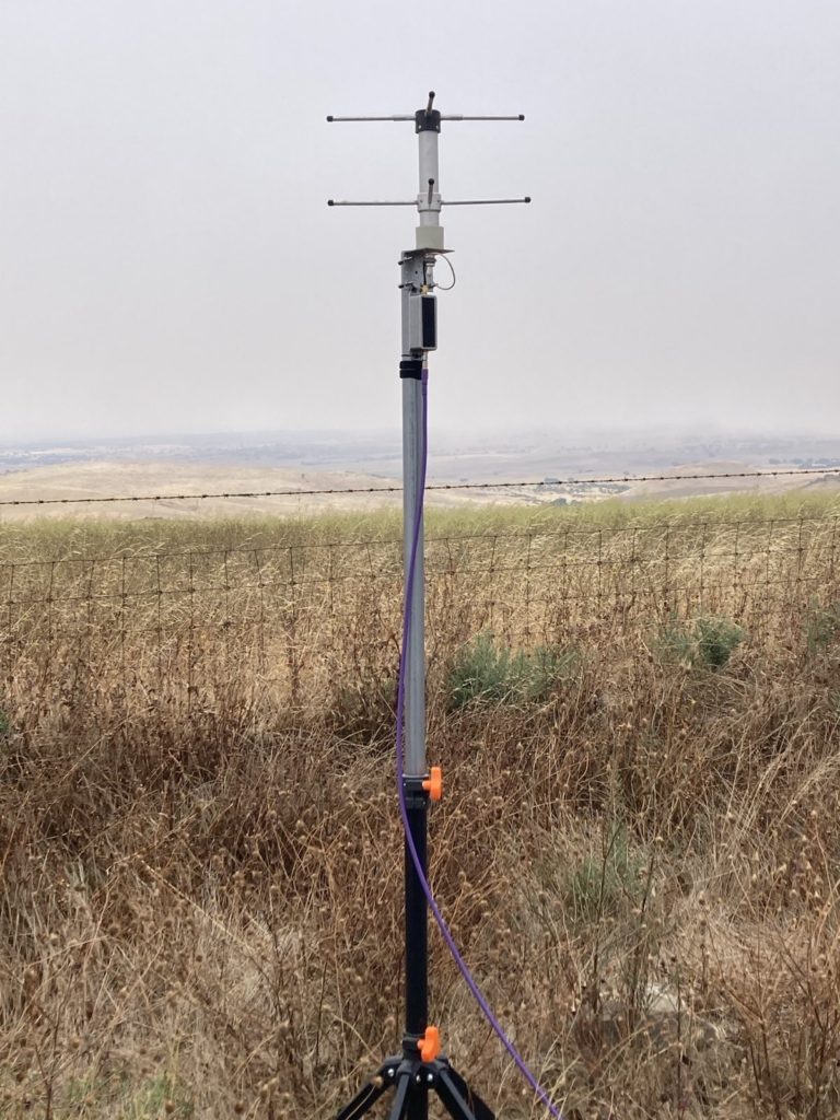
On this “first” flight I was rushed for time and didn’t have time to sort out an antenna. I usually track balloons with Peter VK5KX, so I was intending to plug my box into his beam, but due to leaving a RF adapter behind, I instead used a separate 70cm Turn Style antenna mounted to the side of Peters car. Both Peter and I were surprised just how well this simple antenna worked, so the whole idea of a Turn Style antenna, remote mounted preamp sitting a top an Aldi Bike Stand was born. You can see this antenna system I built for the SHSSP 2023 flight below, again all from my junk box and rediscovered treasures.
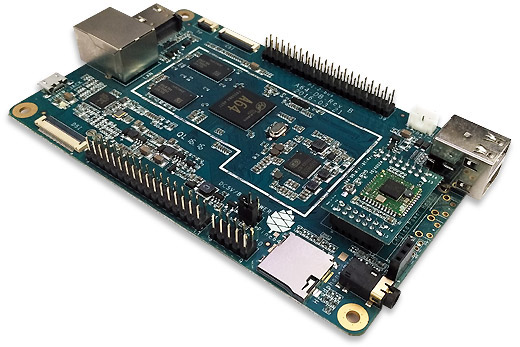
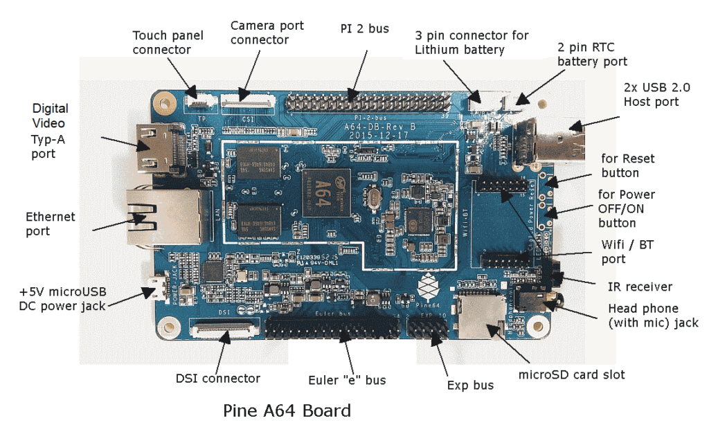
Knowing that I needed another Pine A64, I reached out within my local radio club to see if any of these SBC’s might be languishing on other junk boxes. I’ll give a shout out to Josh VK4JNA who gifted me the third Pine A64 in the photo below. It too was the KickStarter model sporting 2GB of RAM and came with the optional WiFi interface.
It was also during these first flights both Horus 58 and the SHSSP 2023, that after a period of time the software decoders would crash or lockup and stop responding. This wasn’t hard to find by placing ones finger on top of the processor, they were getting too hot and were thermally throttling the clock until the software maxed out the processor and crashed. This was more of a problem for Wenet systems than the 4FSK binary telemetry. Adding some stick on heat sinks didn’t improve things either, it just let them run for a further 10-15 minutes before crashing again. So it was from this that the PineA64Fan project was started, that added a separate software controllable Fan and a DC-DC converter. I’ll go into further detail about this fan controller and power supply in a later post, as it on it’s own has a great story to tell.
I was also thinking of how to power this unit in the field without purchasing a separate Lithium battery. I was watching YouTube one afternoon when I saw someone powering their 100W HF Radio from a Ryobi 19V battery using a DC-DC converter. What a great idea !!! When designing the PineA64Fan I used a DC-DC converter that matched the Mikrotik router input voltage range of 9-30V DC. This meant everything in the box would work nicely from from my 19V Makita batteries I have for my power tools that sit in the shed and are only used on weekends. With 90Wh of storage, this could easily power this entire box for the duration of a balloon flight, which is typically 4 hrs or less.
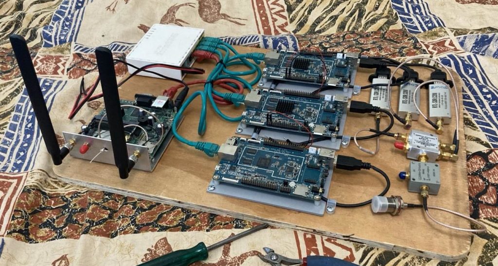
So below is the photo that finally realises the system diagram above.
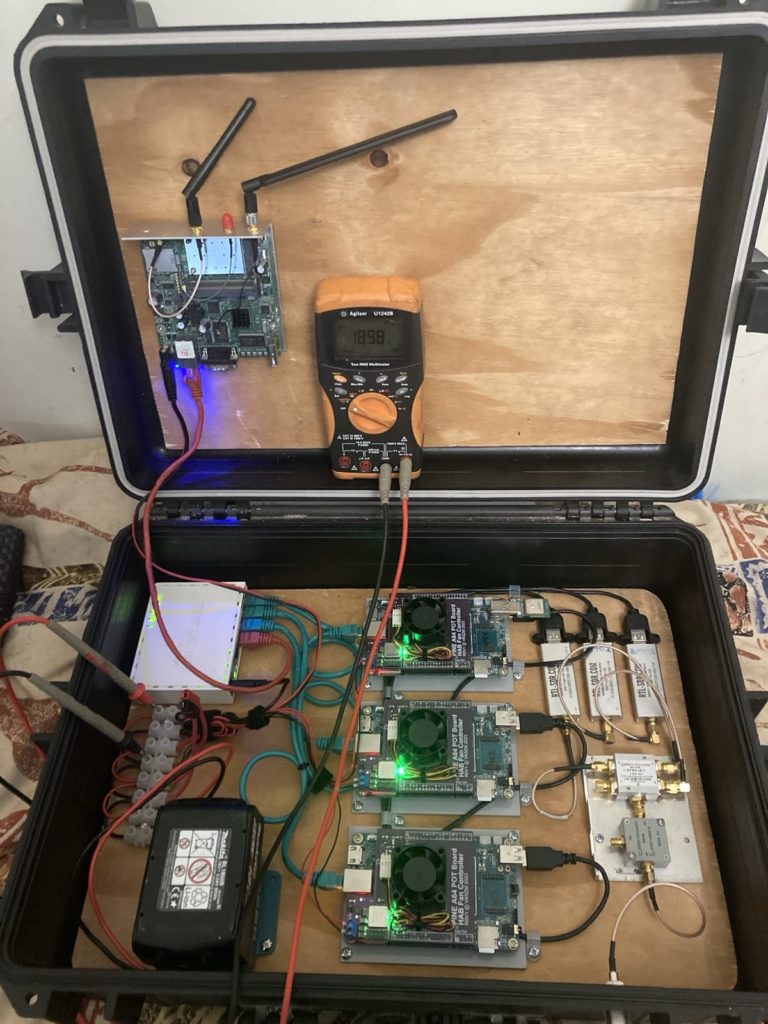
Here we have three Pine A64 SBC’s each with their own RTL-SDR. There are Mikrotik routers to connect the software decoders to the outside world and let them upload the data to the internet. All three Pine A64’s are rocking custom DC-DC converters and software controllable fans, that chime in and out as the processor temp gets above 50°C. As can be seen in the lower right of the case a Bias-T DC injector is used to power the LNA up by the antenna and the SDR’s are connected by a surplus 4-way splitter. Perfect, at least for now.
Next Steps
The system above was realised just before the Horus 60 flight in August of 2023. Which was a special event to celebrate the Amateur Radio Experimenters Group 25th Anniversary. For the eagle eyed reader, you may notice in the Bias-T wiring is not quite finished and that in the Horus 60 write up my callsign does not feature prominently in the logs.
I’ll continue this story and the reasons for the above however in a latter post…