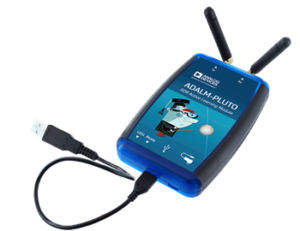
Recently I came across a novel way to get the ADALM Pluto to generate a 10GHz signal. Jay Francis presented a minimal ADALM Pluto 10GHz transceiver system that used a commercial LNB and some Mini-Circuits high pass filters, to pick off the 3rd harmonic from the TX output. You can watch his video below.
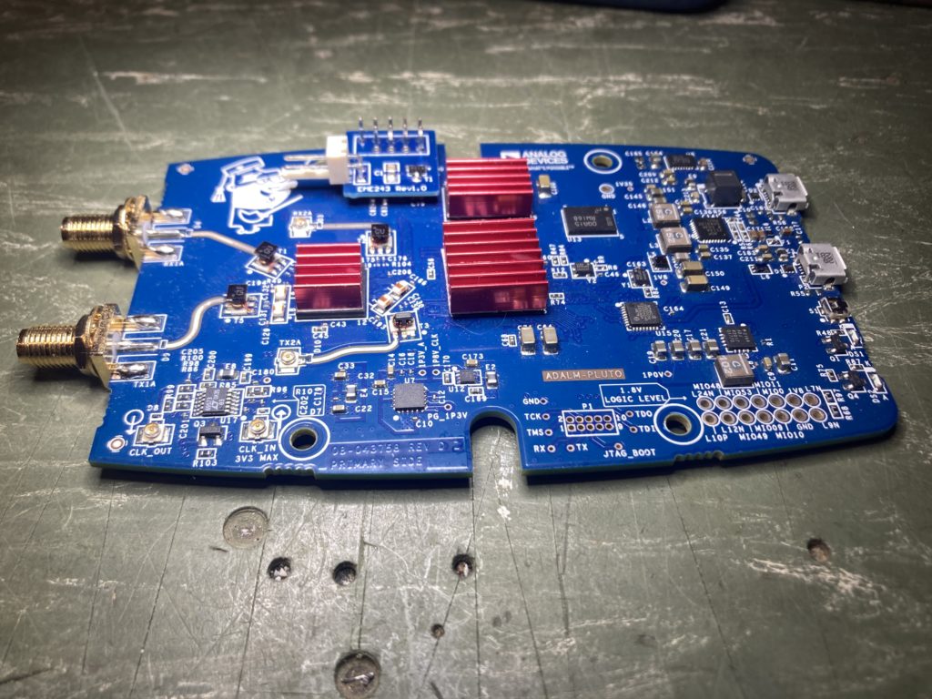
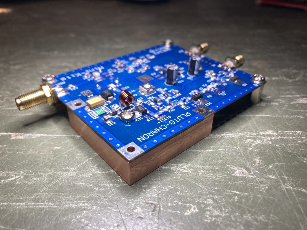
This got me thinking, could you actually build a 10GHz transceiver from the ADALM Pluto like the 23cm Pluto Charon kit I’ve been working on ?
Now I don’t have any of the Mini-Circuits high pass filters and they were a little expensive to get shipped to Australia, but I did know of a 10GHz Frequency Multiplier kit from Minikits being manufactured locally. The Minikits kit comes with a GAL-39, 10GHz pipe cap filter and a NLB310 post amplifier that can be assembled on a universal microwave board. Whilst designed to double a 4-5GHz signal up on to 10GHz, it can also triple a 3-4GHz signal with a bit of tweaking and fine tuning. This was perfect for what I was planning with the ADALM Pluto, so one was ordered and I had to wait for the postman for it to arrive.
While the Minikits multiplier was on its way I also stumbled across N1BUG’s YouTube channel, where he walks you through how he assembles 10GHz pipe cap filters in his workshop. It was quite clear that some “real” heat is required, so I also purchased a Chinese made hotplate to assist with additional heat when soldering the cap itself. You can find more about that adventure here.. So far I’d spent less than the cost of two Mini-Circuits high pass filters.
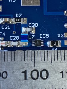
I’m now sure that 10GHz pipe cap filters look bigger on the computer screen than they do in real life. I was genuinely surprised just how tiny they were. I was also questioning the purchase of a hotplate.
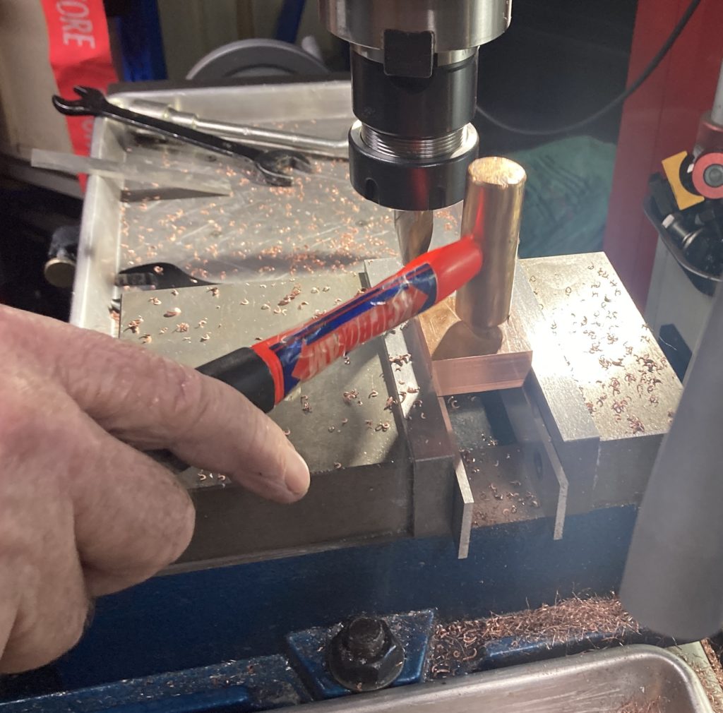
Following the Minikits multiplier kit instructions, I first drilled and tapped a M4 hole in the pipe cap, prepared the probes, modified the board to accept the pipe-cap and then proceeded to solder it down. Since I was using a hotplate, I decided to solder the pipe-cap down first, then solder the probes in after as suggested by N1BUG. This meant I needed to pay attention to the probe straightness and length, so that they would land in the right place once assembled. I was OK with this as I can see the probes through the M4 nut in the top using my microscope before and after soldering.
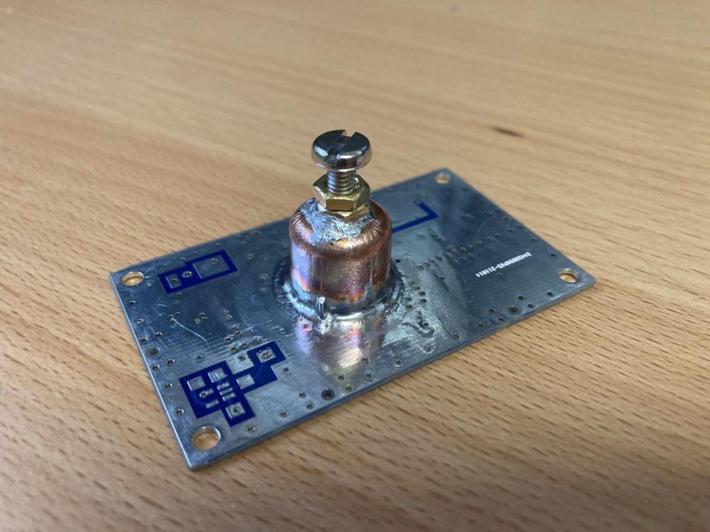
Now soldering this pipe-cap was genuinely difficult and the hotplate certainly made the job much easier. The flux that I used was not that great, I must try to find some of the really gooey sticky flux that N1BUG was using. However I persevered with my Hakko 50W iron wound up to +450°C with a K-tip and some 0.7mm solder rings, tacking and working my way around the cap. Once I’d placed sufficient solder, I then broke out the hot-air gun set to +400°C and re-flowed the joint, which gave me a much neater and more uniform appearance.
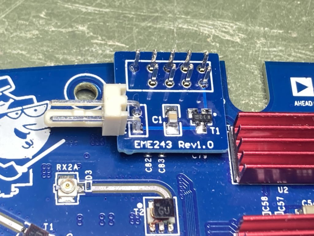
Below is the board after soldering and once I’d cleaned up the excess flux. The Minikits PCB has quite a few holes in the plane, so I used compressed PCBA flux cleaner blown in through the nut to make sure no residual flux was present after soldering. Likewise a small file and knife were used to clean up the blobs of solder around the nut.
For my first attempt at soldering pipe-cap filters I’m happy with the result. I found the hardest part soldering the nut to the top, mainly due to difficulties applying flux and getting the solder to wick to the nut and cap evenly.
So the next steps are to insert the probes and build the associated amplifiers and then test and tune. More to come.