For a while I’ve been building small projects and widgets with combinations of either the Arduino Micro or Leonardo’s. These platforms both use the Atmel ATmega32U4 which is now owned by Microchip. So while working on a recent “ham radio widget” I decided to embed my own custom made Arduino based on the micro platform. This design used DIN rail enclosures which require a fairly funky shaped PCB, so it was time to take the plunge and stop using modules purchased from eBay.
Finding a suitable schematic and parts list was not difficult, laying out the PCB was also uneventful. Since this module would be mounted vertically in an enclosure, I decided to simply squash up the pins on the micro into a double header. This was neat as it then allowed me to re-use the standard Arduino Micro pin map. Anyway a picture speaks a thousand words;
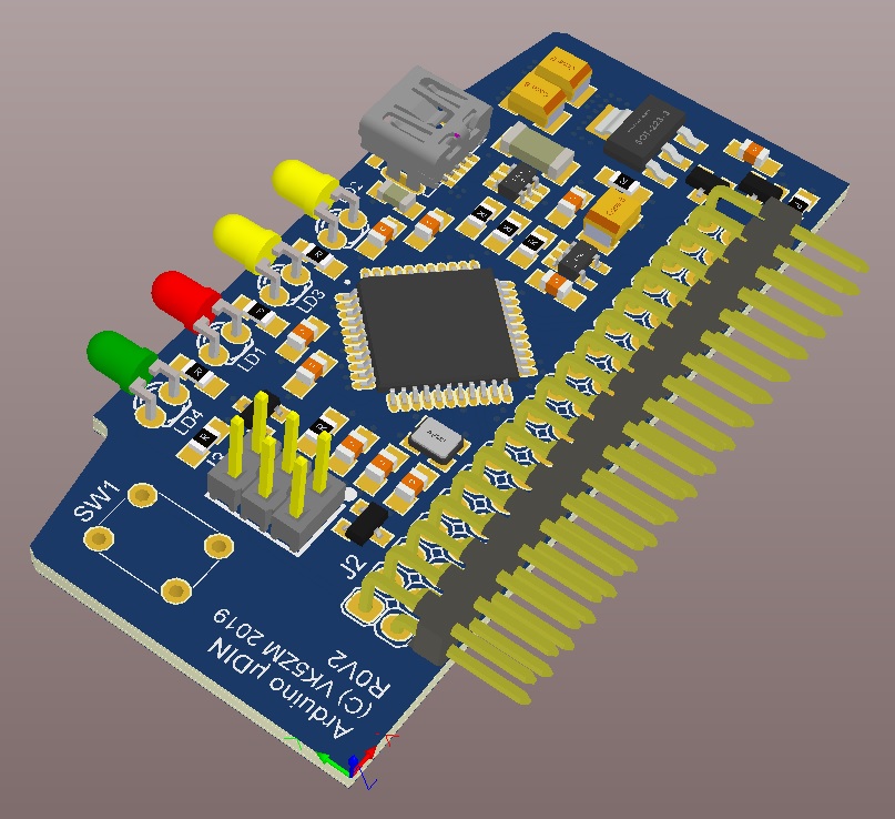
This board is fairly straight forward by design, however it did end up requiring 4 layers to fit within my enclosure with components I could see with my naked eye.
Once built I could then use the 6 pin ISP connector which you can see in the foreground above and my trusty AVRisp mk2 programmer. So now for the crux of the problem and the reason for this post, programming the bootloader.
Since I use AVR Studio and my AVRisp mk2 for professional software development, I had not swapped the usb drivers to libusb-win32 which meant I could not simply use the “burn bootloader” option in the Arduino IDE. So I had to do it the “hard way”.
After a bit of googling I found the bootloader hex file was already on my machine conveniently located within a the standard Arduino IDE directory. I found it in the following sub-directory here;
hardware\arduino\avr\bootloaders\caterina\caterina-micro.hex
The next question is what fuse settings are required. Now I struggled to find any references with practical solutions to this question on google. Searches ended up taking me off to ATmega328p or Arduino Pro bootloaders, not the micro. There are a many different fuses that can be set and if you get it wrong you can brick your processor, so playing around can lead to bad things.
Anyway after much nashing of teeth I found a practical guide to setting the fuses for a Leonardo, so I figured they should be the same or similar. So before simply blasting in these fuses I spent a bit of time to understand what exactly would change. There was nothing sinister there other than turning off the JTAG (unused) and swapping to an external 16MHz oscillator, jeez I hope I’ve got the right crystal and caps.
Below is the fuse settings I ended up with;
Low:  0xff
High: 0xd8
Ext:  0xfb
After programming the FLASH and fuses I then unplugged the programmer and external power supply and attached it to my PC via USB. I was happily greeted with detected new USB device, installing drivers, device is ready to use on COM62. Phew it worked !
All that was left was to fire up the Arduino IDE and create the ubiquitous blinky led program like so;
void setup() {
  // put your setup code here, to run once:
  pinMode( 13, OUTPUT );
  digitalWrite( 13, LOW );

}

void loop() {
  // put your main code here, to run repeatedly:

  delay(100);
  digitalWrite( 13, HIGH );
  delay(100);
  digitalWrite( 13, LOW );
}
Hitting the “upload” button saw the code compiled, AVR dude did it’s thing and my RED led flashing merrily. Problem solvered ! Now to continue putting these modules together and getting this board setup in PlatformIO.