Recently I came across a novel way to get the ADALM Pluto to generate a 10GHz signal. Jay Francis presented a minimal ADALM Pluto 10GHz transceiver system that used a commercial LNB and some Mini-Circuits high pass filters, to pick off the 3rd harmonic from the TX output. You can watch his video below.
This got me thinking, could you actually build a 10GHz transceiver from the ADALM Pluto like the 23cm Pluto Charon kit I’ve been working on ?
Now I don’t have any of the Mini-Circuits high pass filters and they were a little expensive to get shipped to Australia, but I did know of a 10GHz Frequency Multiplier kit from Minikits being manufactured locally. The Minikits kit comes with a GAL-39, 10GHz pipe cap filter and a NLB310 post amplifier that can be assembled on a universal microwave board. Whilst designed to double a 4-5GHz signal up on to 10GHz, it can also triple a 3-4GHz signal with a bit of tweaking and fine tuning. This was perfect for what I was planning with the ADALM Pluto, so one was ordered and I had to wait for the postman for it to arrive.
While the Minikits multiplier was on its way I also stumbled across N1BUG’sYouTube channel, where he walks you through how he assembles 10GHz pipe cap filters in his workshop. It was quite clear that some “real” heat is required, so I also purchased a Chinese made hotplate to assist with additional heat when soldering the cap itself. You can find more about that adventure here.. So far I’d spent less than the cost of two Mini-Circuits high pass filters.
I’m now sure that 10GHz pipe cap filters look bigger on the computer screen than they do in real life. I was genuinely surprised just how tiny they were. I was also questioning the purchase of a hotplate.
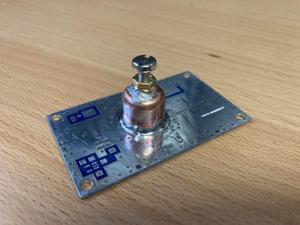
Following the Minikits multiplier kit instructions, I first drilled and tapped a M4 hole in the pipe cap, prepared the probes, modified the board to accept the pipe-cap and then proceeded to solder it down. Since I was using a hotplate, I decided to solder the pipe-cap down first, then solder the probes in after as suggested by N1BUG. This meant I needed to pay attention to the probe straightness and length, so that they would land in the right place once assembled. I was OK with this as I can see the probes through the M4 nut in the top using my microscope before and after soldering.
Now soldering this pipe-cap was genuinely difficult and the hotplate certainly made the job much easier. The flux that I used was not that great, I must try to find some of the really gooey sticky flux that N1BUG was using. However I persevered with my Hakko 50W iron wound up to +450°C with a K-tip and some 0.7mm solder rings, tacking and working my way around the cap. Once I’d placed sufficient solder, I then broke out the hot-air gun set to +400°C and re-flowed the joint, which gave me a much neater and more uniform appearance.
Below is the board after soldering and once I’d cleaned up the excess flux. The Minikits PCB has quite a few holes in the plane, so I used compressed PCBA flux cleaner blown in through the nut to make sure no residual flux was present after soldering. Likewise a small file and knife were used to clean up the blobs of solder around the nut.
For my first attempt at soldering pipe-cap filters I’m happy with the result. I found the hardest part soldering the nut to the top, mainly due to difficulties applying flux and getting the solder to wick to the nut and cap evenly.
So the next steps are to insert the probes and build the associated amplifiers and then test and tune. More to come.
Soldering anything with a large thermal mass is tricky business. Often when faced with this situation I crank up the temperature on my Hakko soldering station well into the +450°C region, wet the tip with solder and try to pour enough heat into the joint to get the solder to bond well. The downside is often the heat is drawn away from the joint, which means you’re heating the joint for far too long and materials start to burn. PCB laminate is typically OK to temperatures of 140-170°C for short periods before they turn brown. Likewise any flux does not get a chance to remove oxidisation and results in contaminated joints.
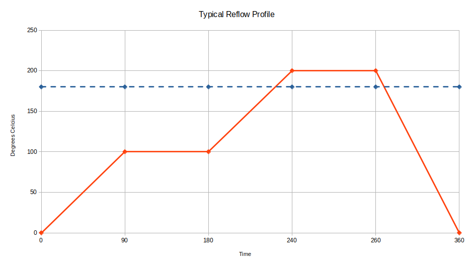
The best solution is to use a hot plate, which will bring what you’re trying to solder to a per-heated stage before you apply the iron. This is effectively a “manual” version of reflow soldering, I’ve tried to draw a typical reflow profile below.
There is a lot of information about the above curve on the internet, needless to say I intend to use the hot plate to give me the preheat and dwell time to activate any flux (first flat part), and then use my soldering iron to melt the solder (peak) and then allow things to cool down.
So the next question is where do you buy one ?
Searching in various places I noticed that online there was a plethora of some cheap Chinese hot plates for what seemed like very little money. I couldn’t build one for the price being offered. Wondering what was inside I found the following tear-down video, which suggests while they work there are some potential issues with their electrical safety.
Curious I ordered one and waited for the postman to deliver. Like the author above I found that the internal wiring of this unit was non-compliant to Australian safety standards, which shouldn’t come as a surprise as the unit had no safety markings at all; making these units technically illegal to import and use.
However I’m fortunate to work within the Electrical Industry, so I have access to the relevant safety standards and could modify my unit to make it compliant and therefore safe. Before anyone asks, no I cannot provide details of what I did to my unit. There are more things to consider than just the earthing, as was done in the above video. It took me quite a number of hours to fix the issues I found with this unit. I would suggest that others look for and buy hot plates that have the necessary RCM/UL/CE markings relevant to your country.
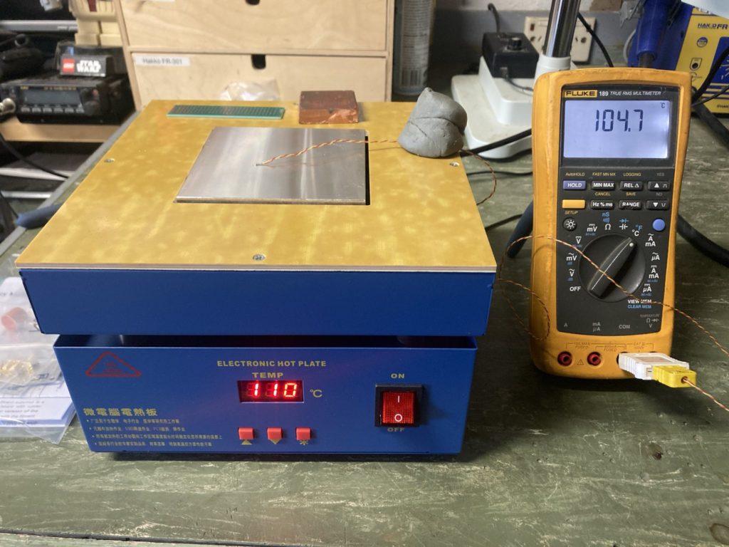
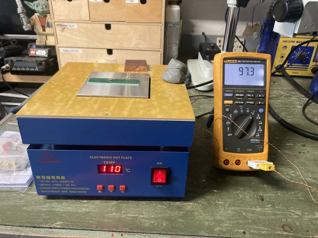
With the safety issues resolved I could set to testing the operation of my unit to see if it indeed worked. I placed a K-Type thermocouple into my trusty multimeter and set too testing various temperature settings with various materials.
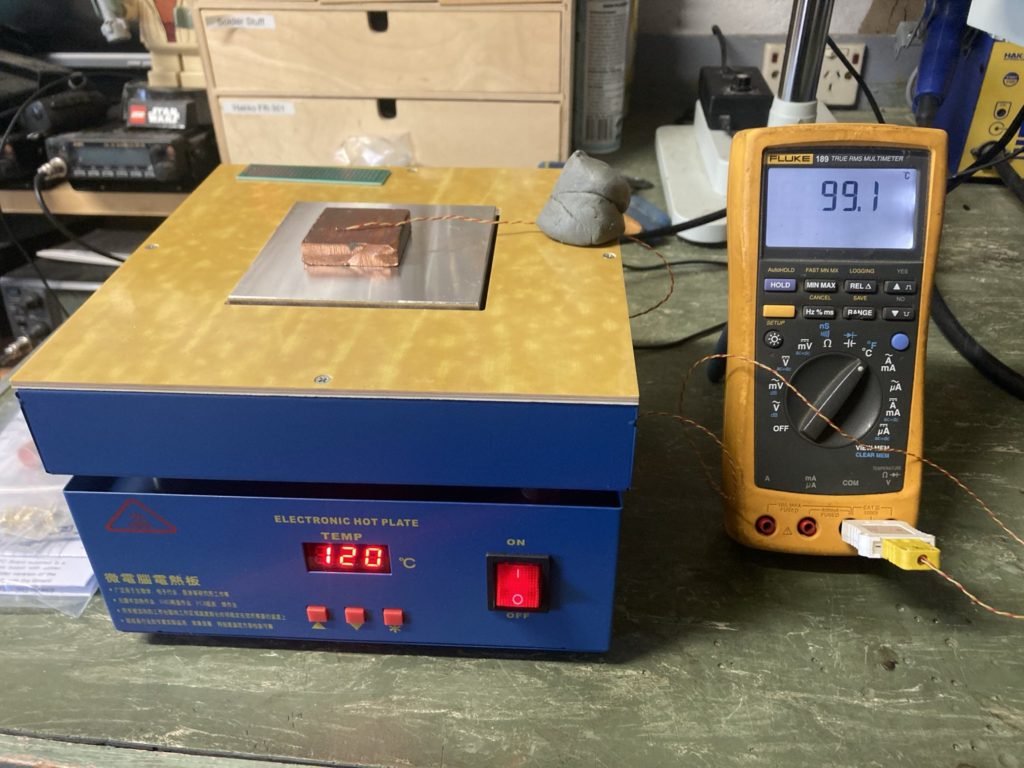
PCB LaminateCopper Block
With the thermocouple sitting on the middle of the plate, the 7-segment set temperature and temp reading on the multimeter were close enough for government work. In case you were wondering +100°C is hot, so best not to touch the plate or attempt to pick up the items left on the plate for any period of time, ouch it will burn.
I do like the fact the hotplate on this unit is small, with a fiberglass surround. The fiberglass surround allows me to place my hands either side of the hotplate, without fear of being burnt. It also means I can use mechanical weights to hold things down as I solder them to various places. Hence why I could use a ball of blue-tac to hold the thermocouple wire.
On the 7-segment display the right most decimal point will flash as the heater element is switched on and off. Watching the hotplate warm-up and the 7-segment display decimal point, it would appear that some form of pulse integral control loop is being used with its own internal temp sensor. The plate warms reasonably quickly but will slow down as it approaches the set point, there was no signs of overshoot which I was happy with.
Once the main hot plate temperature was stable, I placed an old piece of PCB laminate under the temp sensor and watched the temperature on the thermocouple slowly increase. Needless to say after a couple of minutes the temperatures once again were close enough. I did adjust the set point up to +110°C as there is some noticeable thermal resistance across FR4 laminate. Likewise the copper block took a little longer at 5-6 minutes to warm up to temp, again I had to increase the set point to +120°C as copper is very good at dissipating heat, so this was of little surprise. All in all the thermal performance of this unit was good.
This hot plate should have at face value represented a real bargain, had it not been for the internal wiring and safety issues. I cannot stress how important electrical safety is, mains voltages are lethal; so please consider purchasing another unit that has the relevant safety marks.
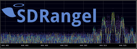
So it’s been a while since I’d looked at my ADLAM Pluto SDR project, to complicate matters I’ve also recently switched to Linux. So it was time to see if I could find new SDR software to drive it.
After a few false starts and some trials and tribulations, I finally settled on SDRangel. I’ve used this app before to demodulate a High Altitude Balloon payload that transmitted a quirky DVB-T modulator using a RTL-SDR and Ubuntu Laptop.
So the only problem, SDRangel is written to natively run on Ubuntu, Windows, Mac and the rest of the distros can either use a snap package or compile from source. Sigh. Linux Mint does not like snaps, LMDE uses only flatpak’s.
SDRangel Flatpak
Now I’m not a big fan of flatpak’s either, to me they are in the same boat as snaps and docker images, unnecessarily slow, however after reading how to compile SDRangel from source, a flatpak was certainly the fastest and easiest way to let me try the software and see if I can get this working.
Thankfully I found SDRangel on Flathub. The following was all I had to do from a command line to install the flatpak, installation instructions were found here.
After a short time downloading and installing it was ready.
SDR plugable UDEV Rules
SDRAngel requires udev rules to be added for the most common SDR’s, since I also intend to try RTL-SDR’s at some point, now as as good as any time to install.
The udev rules can be found here on the SDRangel GitHub repo. I simply downloaded them in a zip file to my local downloads directory, unzipped and moved them into /etc/udev/rules.d. There is an installation script (install.sh) in that same directory as the downloaded udev rules you can use or read for inspiration on the linux commands necessary.
If you find that you still can’t access these devices, check your user has the right permissions to use USB or network devices, trap for young players and outside the scope of this post. Google and Duck-Duck-Go has lots to say on this topic.
Flatpak Permissions
Before starting SDRangel I also loaded Flatseal and checked what permissions the SDRangel flatpak was requesting. Always pays to review flatpaks using Flatseal, I’ve found a few packages that had some very odd permissions and didn’t work on LMDE out of the box.
It makes sense to me to grant SDRangel access to the network, PulseAudio sound server, GPU acceleration (if used), All devices (i.e. SDR’s) and the “Run in Background” option. This is the config that worked for me, YMMV.
SDRangel Configuration
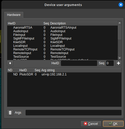
Once SDRangel is loaded, we’re greeted with a big blank screen. From here I added the ADLAM Pluto by clicking Preferences > Devices > User Arguments
I then added “PlutoSDR” in the HwID field, left seq as 0 and hit the ‘+” button which is the add symbol. I then selected the PlutoSDR entry in the lower pane, added “uri=ip:192.168.2.1” in the Args field, and hit OK. After I’d finished my config screen looked like this. Note my IP is the default PlutoDVB value, you can find what yours is set to in the config.txt file from the Pluto storage device it presents when connected to a PC. Now apparently you need to restart SDRangel for this to have any effect. YMMV.
Adding a RX Device
I then added an RX device by clicking on the menu button just to the right of the purple button with a play symbol in it. If you hover over each button, a pop up appears telling you what the button is. From the drop down box, I then selected the PlutoSDR entry which was right towards the bottom of the list.
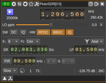
Two screens appear, but we’ll concentrate on them one at a time. I configured the Receive window like this, more info here;
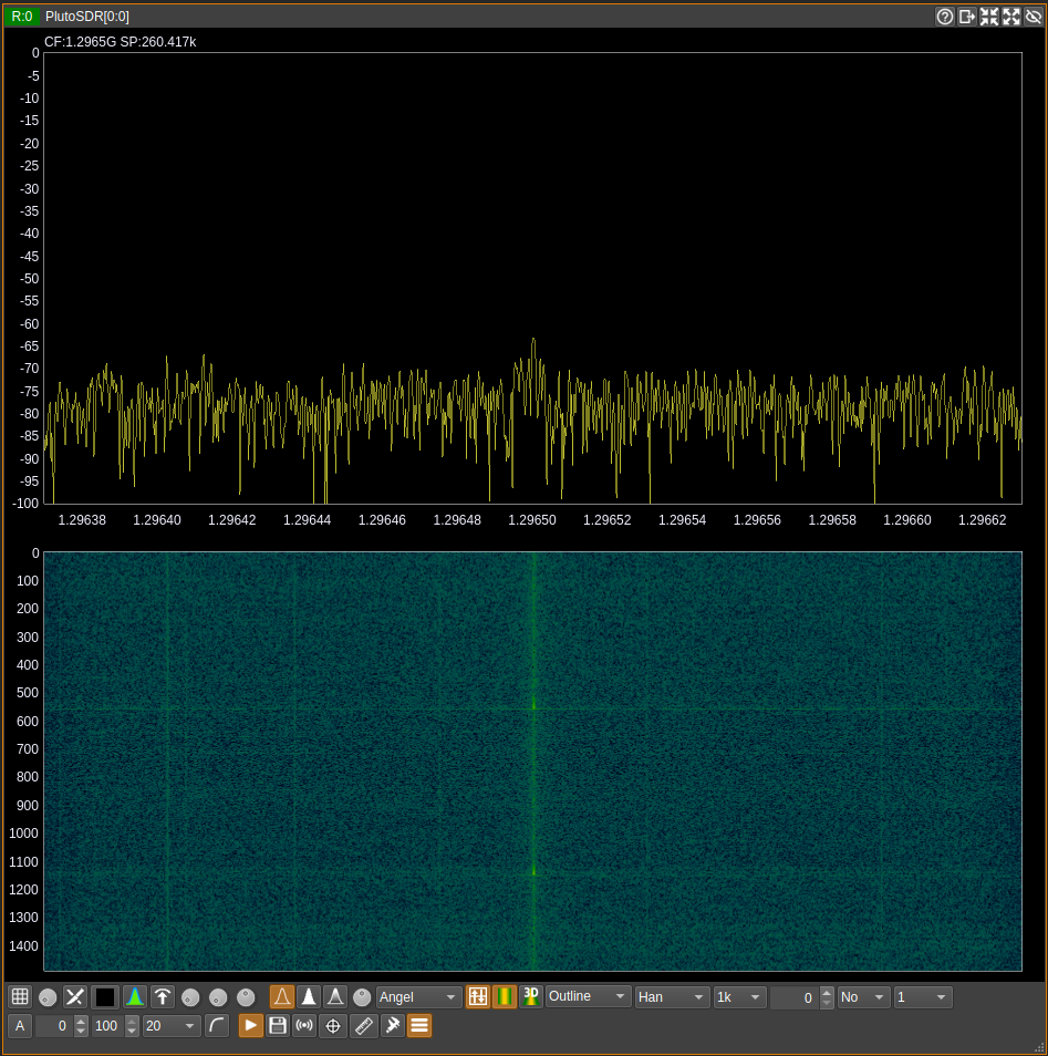
Now the thing to note. I’ve twiddled the sampling rate for reasons I’ll explain in another post. You should find the initial settings of 2.5MHz work well enough out of the box. I’ve increased the decimation from 1 to 8 in the S field, likewise I’ve selected “slow” AGC. If you then press the purple button with the white play symbol, you would see the next window start to do something interesting like this.
I didn’t change anything here, the out of the box config just worked for me. Now you might notice you don’t hear anything, that is because you have to add a channel/separate demodulator. On the receive window, just to the left of where “PlutoSDR[0:0]” appears is a button you can click to add a channel.
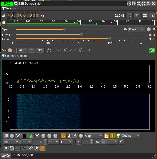
From the pull down box I’d choose the SSB Demodulator, which will appear on your screen. I configured it like this;
I had to play around with the sound settings, especially the audio settings which were hidden under the green speaker symbol (right click) on the right side of the screen just above the Channel Spectrum display. It is worth spending the time to read the documentation on the SDRangel website, once you realise that each part is a software plugin and how configurable this system is things get more interesting.
By the time we have the receiver configured, the spectrum display happening and a channel defined, audio should be appearing out of your speakers. If not then you’ll need to spend a bit more time debugging what’s happened with PulseAudio, mine just came to life.
I’ll also mention that if you try the Narrow Band FM channel plugin, there is a hidden squelch power threshold setting, that you need to wind down to -100 for it to open the squelch and produce white noise. It’s just to the right of “Sq” and a funny button with a triangle on it, you’ll see what I mean.
Adding a TX Device
I’m not going to reinvent the wheel here. I found a great article on the web and a video on YouTube from SignalsEverywhere that explained how to configure the ADLAM Pluto to transmit. You can find the original article from the RTL-SDR site here and the video embedded below;
Putting it all together
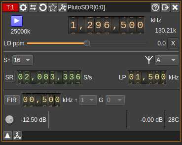
To prove that I could get this all working, I put the receiver on 1296.5MHz with the settings previously shown. I configured the transmitter slightly differently adding further decimation to reduce the effective bandwidth. You can see this below;
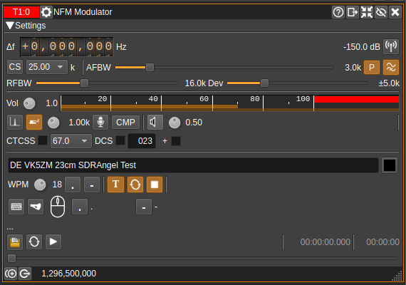
I then added a Narrow Band Modulator, by clicking the button just to the left of where “PlutoSDR[0:0]” appears in the menu bar (just like a channel button in a receive window) and selecting NFM Modulator from the drop down box. You then configure like so, based entirely on SignalsEverywhere’s YT video.
If you click on the purple button with the white triangle on the TX window, you should be greeted by CW being sent. Just so there was proof, I made and uploaded my own video.
In the above video the audio is being demodulated by the Icom R10 on 1296.5MHz NBFM just so that there was a “Real Radio (TM)” involved. The ADLAM Pluto is transmitting approximately 0dBm into a dummy load. The ADLAM Pluto receiver is displaying the received signal and waterfall, I didn’t bother with a channel/demodulator to listen to my own transmission, the R10 was doing a good enough job on it’s own.
So now that I’ve got that working, I can start to experiment with the ADLAM Pluto and some microwave multipliers to get me up into the higher bands. I also need to check it will still key the Pluto Charon kit and modify as necessary. More to this story shortly.
So recently I upgraded my computer to something more modern. Jumping seven or so I7 generations has brought my personal development machine from the mid-naughties back to relatively recent hardware. This time I’ve gone for a second hand one owner Dell Precision SFF desktop, which sat on my desk at work for the past 4 years, which was duly purchased when the lease expired.
Microsoft however with all their AI shenanigans incentivised me to make the switch to a Linux desktop permanently. So it was goodbye Windows 10 and hello Linux Mint, more specifically LMDE. I’m no stranger to Linux, having built and maintained Linux systems since the 90’s, but as a desktop, well that is all new.
I chose LMDE in preference to standard Linux Mint after a few arguments with the later versions of Ubuntu and their slow evolution towards snaps, which kept robbing my old laptop hardware of resources. I switched to Linux on my laptop more than six years ago and it’s been great.
For quite a few years I’ve been using and given priority to Open Source apps for my Electronics and Radio development and I was really down to one or two Windows only apps when I switched. Nothing a Virtual Machine booting windows couldn’t solve using Oracle VirtualBox, especially on this machine with newer hardware and enough RAM.
So far I’m impressed with LMDE as nearly everything has worked out of the box, including printing. So much easier than Slackware compiling everything from source back in the day. I was however caught out by secure boot and VirtualBox, which lead to learning’s on the DKMS driver signing mechanisms, which ultimately saved me from NVIDIA Driver horrors; which is the subject of another post I must get around to soon.
It’s now been more than three months since I’ve switched and I’ve not needed to switch back, on-wards and up-wards !