Rubidium Reference – BITE

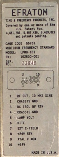
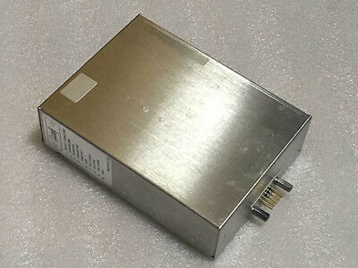
The Efratom LPRO-101 has a Built in Test Equipment (BITE) signal available on Pin 6. This pin is connected to the 5V logic within the module. When the BITE signal goes LOW (0V) then the physics engine has achieved lock within roughly +/-5×10-8 of it’s absolute frequency. Thankfully it can do this within 3-4 minutes of operation.

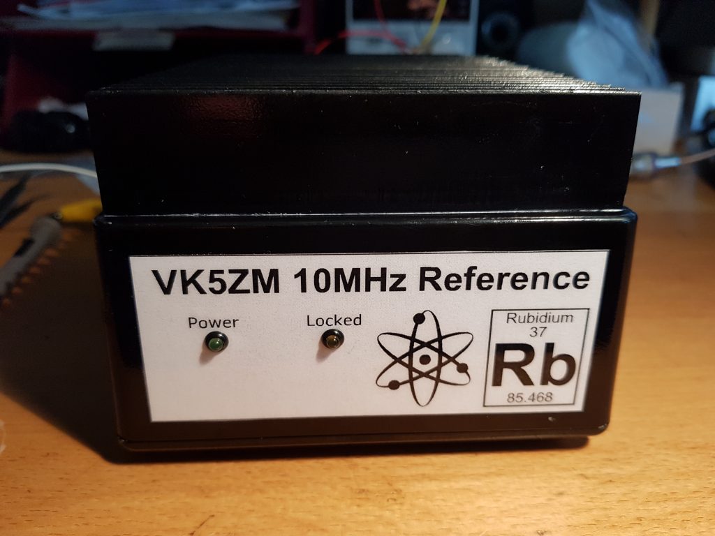
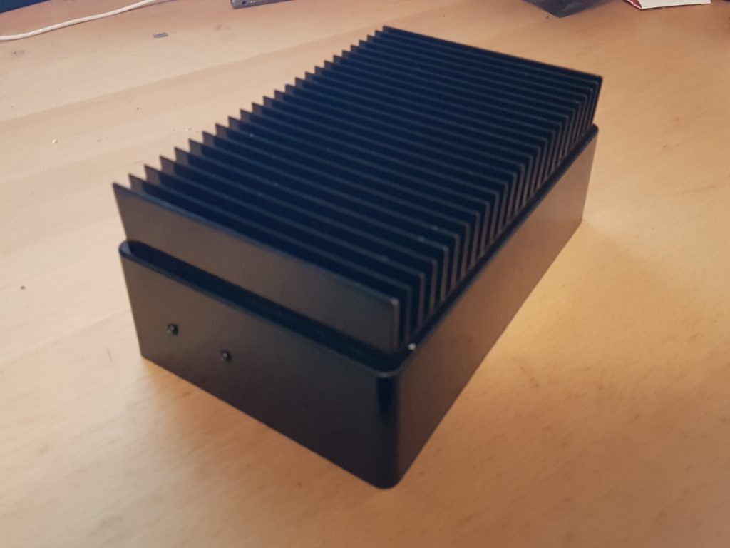
When I’m out in the field it is certainly useful to know what the reference is doing or if something has gone wrong without having to pull it apart and get out a multimeter. So on the front panel I’ve placed two LEDs one for power and the second to show lock.

The lock signal will be nothing more than the BITE signal inverted, which can be done with one transistor. I’ve seen some quite elaborate two and three transistor circuits, but we only really need one. The circuit I’ve draw below is straight out of my engineering log book, it’s so simple I couldn’t be bothered firing up Altium to draw it;

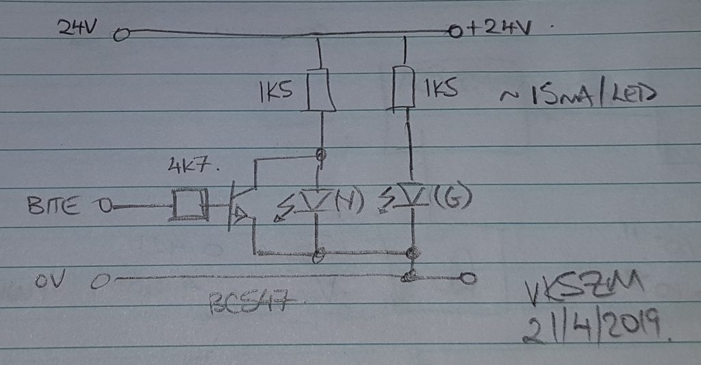
Basically we use one transistor to shunt the LED so that it is OFF while the BITE signal is HIGH. There is no rocket science here. With the heaters in the reference drawing 1.2A at startup throwing an additional 15mA through a transistor until it’s locked should be no big deal. The entire current drawn is approx 30mA, they are certainly bright enough in daylight, they might require turning down after using this at night, time will tell.

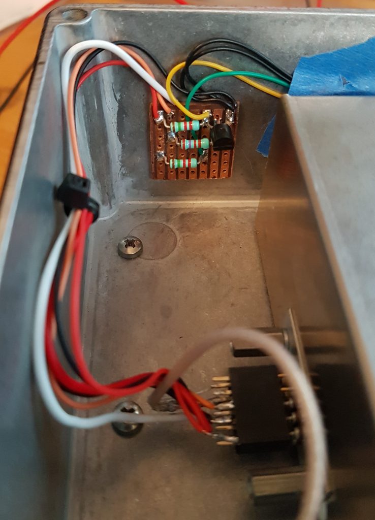
The circuit above is so simple I built it dead bug style on a piece of vero board. I did this so I could simply use double sided tape to hold it to the box and not short anything out.

One minor annoyance I’ve found is at the time power is applied the BITE output remains LOW for half a second or more before it goes HIGH. This means that the locked LED will light momentarily, then go out for 3-4 minutes as the reference warms before it lights again. The video below shows what I mean, for such a simple circuit I’m happy to put up with this feature;

You can hear the first click of the power supply, the Locked LED will light and go back out again. This was done when the reference was already warm so it takes less than 20s to regain lock again.

Anyway I’m certainly pleased with the simplicity. However now I’ve got ideas to use a micro a DAC and give this thing some intelligence. More notes in the log book for when I find time to come back to this again, for now it’s time to get out in the field and use it in anger !

Posted in EME

Rubidium Reference – The Retest

It can take a GPS disciplined oscillator a while to stabilise and settle down. When I first tested my new free running rubidium reference the GPS disciplined rubidium reference had spent no more than an hour making it’s observations and corrections. So I left it running over night with the intention of measuring things again in the morning.

So after 16 hours the frequency error has reduced more than three decades, should be good to go. I also have a precision TXCO reference (SDI FEL-10A) so I thought I’d measure this first and see what sort of stability and accuracy this can achieve. Both the free running TXCO and Rubidium were switched on 30 minutes and left to stabilise before measurements were made;

So that is quite a respectable result, being within +0.318Hz of our 10MHz target. Then for the main event it was time to re-measure the free running rubidium;

So this is a little higher that what was measured last night, but +0.009Hz or +9mHz is still a great result. To put this into perspective if I were to use this reference to lock a series of transverters this is the final frequency accuracy I would expect;

F(carrier) | F(error)
[MHz] | [Hz]
-----------+-----------
50.195 | +0.45Hz
144.135 | +1.30Hz
432.070 | +3.88Hz
1296.070 | +11.66Hz

I think if I were to go higher than 70cm then a GPS disciplined oscillator is in order (there is a Trimble Thunderbolt in a box somewhere), at least I have some idea now what the upper workable limit is. One of these days I may yet get in and tweak the external C-Field input and see if I can tighten this frequency error up a little, that will have to wait for a 12-digit counter.

The free running TXCO also has a reference input so for a laugh I attached the free running Rubidium to the TXCO and waited to see what happened. The lock LED lit pretty much instantaneously and the result was;

Exactly the same as the Rubidium on it’s own. What I do like about the TXCO is the 6 channel output with >120dB of isolation between channels. At least now I have some idea how stable this oscillator is, so now I can start thinking about what I’ll do with it.

Posted in EME

Rubidium Reference – Final Tests

Now the million dollar question is does it work ? Testing one of these rubidium references means you need a reference and counter that’s more accurate that the reference you’re trying to measure.

Fortunately one of my club members has a GPS disciplined Rubidium Oscillator that can attain some silly levels of stability and accuracy. Giving this device a few hours to watch satellites and let it discipline the internal oscillator is enough to then make some very accurate measurements. Even in the first 16 minutes this oscillator is able to achieve a frequency error less than what we need to make our measurements, after a further hour this number decreases yet another decade.

Once you have the uber accurate reference and accuracy you still need a counter with enough digits. This turns out to be something of a problem, all of the frequency counters I can find seem to stop at 8 digits. Which means you can only measure to the nearest hertz.

At work we have been cleaning up more than 25 years of Engineering mess and while we were cleaning we found a HP 5385A frequency counter stashed in a cupboard that no one knew was there, this particular counter can accept an external 10MHz reference. Combine this with a gate time of 10s it’s able to extend it’s display to a full 11 digits, meaning we can see down to the nearest milliHertz. So that just had to come home for the weekend to test it was working you see. They are actually reasonably priced on Ebay, so I can see a purchase coming on in the not too distant future.

So the measurement of my free running Rubidium reference is now rather simple. The GPS disciplined Rubidium drives the external reference of the HP 5385A counter, our test rubidium is then attached to the appropriate input. Then we need to give everything a good hour to reach thermal equilibrium and stablise. We can then make our final measurement.

I’ve not yet placed a thermocouple on the heat sink and made any measurements but it is certainly much cooler to the touch then when I ran it with just the enclosure.

So above is all of the test gear spread out on the kitchen table (shhh !) the GPS cable exits out a door so it can see the sky. The multimeter is reading the buffered Lamp Voltage, ideally this should be between 6-9 volts for a healthy Rubidium. Alas this rubidium probably has only a few years life left in it before it has to be refurbished.

However from this distance it’s a bit hard to read the counter, so here’s the closeup;

That is an awful amount of zeros, however it shows that my free running rubidium is running just +5.0 milliHz fast or +5.0×10^-9 Hz in scientific notation. Wow it works !

As you can see I’m now looking for that 12-digit frequency counter so that I can see just how good this rubidium is.

I’ve also read that it’s possible to trim the frequency of the 10MHz oscillator a little using the C-trim input pin (#7).. Hmm I guess that is how the GPS disciplined Rubidium does it !?! So with a multi-turn pot (10-20T) it may be possible to trim the frequency to be better than 1×10^-10 with luck and crossing of eye’s. However from what I’ve observed this may be pushing the limits of the thermal stability of these units and the error of the GPS disciplined oscillator will start to come into play.

Anyway I’m reasonably confident now that this Rubidium 10MHz reference will be able to keep my Elecraft K3 transceiver locked onto the right frequency for any EME experiments even in the dead of night.

Now I’ve just got to get the LEDs on the front panel working correctly and how I’m going to power this unit in the field. With a power supply requirement of 24V @ 0.45A this isn’t insignificant.

Posted in EME

Rubidium Reference – Front Panel

Usually I don’t bother making intricate front panels for my projects, but this reference just didn’t look right. At the front are two LEDs one for power and the other displays when the module achieves the atomic lock. On the rear is a SMA connector for the output along with power.

So for this project I decided to make a front panel, this Rubidium has some bragging rights after all. I’ve read a few blogs recently that suggested using a printable sticky label covered by one half of those non-heated laminate pouches. So a quick trip to the office supplies shop saw me come home with some Avery labels that take up roughly half a (A4) page and some pouches that are also sticky.

Not having any vector/raster tools on this computer saw me install Inkscape for the first time. I’m impressed, it wasn’t hard for the first time to use many of the functions your looking for are easily found. So the label I knocked together is below;

So through the laser printer it went and then laminated. A scalpel made quick work of the holes for the LED bezels. Then using two drills through the holes for alignment the label was carefully lowered onto the front panel and then pressed firmly but slowly onto the surface to prevent air bubbles. For those that were forced to contact their books for school would be well training in the appropriate technique, otherwise hit the scrap booking blogs and websites.

So here’s the final result;

I’ve since shown this to one of my fellow club members and he’s suggested next time I put a 2D bar code that links you to either Wikipedia or YouTube that then explains what a rubidium reference is. I could even refer them back to this blog… Hmm… I’m going to have to try that one day !

For now however my Rubidium reference has a front panel that says it’s all mine and explains the LED’s. I’m certainly happy with the result.

Posted in EME

Rubidium Reference – Thermal Management

These rubidium oscillators run hot, very hot. The Rubidium lamp chamber is heated to over +106°C before ignition occurs, the resonant cavity is kept at +70°C to maintain it’s thermal stability. This means that heat needs to go somewhere, usually to the ambient if we can.

So when I decided to mount my rubidium module to the bottom of my die-cast enclosure I’ve used silicon thermal transfer tape. This material is roughly 0.5mm thick, sticky on both sides and came in a 100x100mm sheet. This is thick enough so suck up any mechanical differences between the die-cast box and rubidium enclosure ensuring the thermal tapes makes contact. This material is typically available from Mouser, Digikey and Element14; however I purchased mine from our local electronics shop Jaycar (NM2790).

Would you believe in the rush I didn’t take any photo’s of this silicon thermal transfer tape being applied, maybe on the next unit I’ll remember !

A few back of the envelope calculations suggested that this material would achieve a worst case thermal resistance of 0.085°C/W, provided the mounting screws were done up tight. This then ensures the difference in temperature between the rubidium module and enclosure could be limited to less than 3°C (worst case).

So to satisfy my own curiosity I decided to mount the rubidium module to the die-cast enclosure without a heat sink and see how hot things got. After 30 minutes of continuous operation the enclosure over the top of the physics engine was found to be the hottest, reaching +40°C in an ambient of +25°C. In a home or lab this would probably be OK, but I’m intending to take this reference with me out into the field in ambient temperatures up to +50°C.

The reference guide recommends using a heat sink with a thermal resistance better than 2.0°C/W in these situations which sounds like a good idea. So just a back of the napkin double check;

Rth(Si) = 0.09°C/W   [silicon pad]
Rth(Al) = 0.008°C/W [die-cast box]
Rth(JG)= 0.25°C/W [jump grease]
Rth(HS) = 2.0°C/W [heat sink]
Tambient = +50°C [typical Australian Summer !]

Rth(total) = Rth(Si) + Rth(Al) + Rth(JG) + Rth(HS)
= 2.438°C/W

Pdiss = 28.8W (peak) 9.6W (average)

Trise = Pdiss * Rth(total)
= 28.8 * 2.438
= 67°C

Tmax = Tambient + Trise
= 50 + 67
= 117°C

OK so this will just scrape in under the typical +125°C limit for silicon devices within this rubidium module. Ditto on the capacitors.

Placing thermal paste between the heat sink and enclosure will also ensure the thermal dissipation is kept low. I prefer to call thermal paste jump grease. Since from the moment you open the tin it will somehow jump on to your elbow and then get everywhere. It’s tricky stuff to master.

I didn’t see any point placing this grease towards the bottom of the box, since the majority of the heat comes from under the physics engine. Once this was done then the heat sink was married up to the die-case enclosure, it’s a good sign when you can see the paste squeeze out from under the heat sink slightly.

This then just requires a bit more cleanup with Turpentine, the odourless stuff is best ! Just watch this stuff, since it has a habit of squeezing out for a while if applied too thick.

Posted in EME

Rubidium Reference – Machining

The Efratom LPRO-101 reference guide has the necessary drill pattern for mounting the reference oscillator within an enclosure. The one thing to watch, that caught me out, is the two screws in the middle are not on the centre line of the unit, it’s offset. It doesn’t look like it until it’s too late. So make sure you measure twice and drill once or you will write off a die-cast box or two.

This module is somewhat difficult to mount to a heat sink since the spacing of the mounting holes do not line up neatly with any heat sink profiles I could find. So instead I’ve mounted my module to the bottom of my die-cast enclosure with countersunk screws and will then mount the die-cast box to the heat sink. So the die-cast box is effectively sandwiched between the rubidium reference enclosure and heat sink.

As a graduate engineer I was once shown by a senior tech a great way of marking up and drilling die-cast boxes without marking the face. Basically you cover the areas where you want to drill holes with masking tape and use a pencil or drafting pen to mark the tape. You can then centre punch your holes, remove the tape and drill. Below is the bottom of my Hammond 1590D enclosure marked out with the holes for the Rubidium reference.

Here I’ve drilled the mounting holes for the Rubidium for a test just prior to making the decision to drill the heat sink holes. After drilling and tapping all necessary holes the box and lid received two coats of etch primer and then two coats of gloss black. There are times I just hate gloss black, it shows all the imperfections and it is so easy to mark. I’ve learnt that if you want a good finish, make sure you spray and bake the final coat in a small toaster oven set to 70-80°C for an hour. So after painting it looked like this;

Paint has a terrible thermal conductivity, so I’ve taken the time to mask off the top of the box so I can put thermal paste (white goo aka jump grease) between the heat sink and box at final assembly. Above you can see the black heads of the 1/2″ 4-40 UNC 2B screws required to pull the rubidium up against the lid. In the thermal management section I’ll talk a little more about how I’m going to get the heat out of this module. This is what it looks like when turned over;

If you look closely you’ll see it’s centred within the enclosure, which means I was paying attention to the two holes in the middle of the enclosure being offset (*grin*). There are also holes in either end of the enclosure for LED’s, SMA connector and power to be connected when final wiring takes place.

Once the body of the box had been done I could turn my attention to the heat sink that mounts on top. Again I used my tape mask trick to mark and drill the holes that went between the fins. Each of these holes was tapped with a M3 thread so that screws could be mounted without the aid of nuts and washers.

The heat sink unfortunately was a little large and had to be cut down. I am luck to have a workshop at work with an engineering band-saw fitted with a bi-metal blade. So it wasn’t difficult to cut the heat sink down to the right size and then repaint. One of these days I must learn how to do black anodising with dye. So dry assembled we get this effect;

Which looks rather snazzy. Now to finish off the thermal design.

Posted in EME

Rubidium Reference – Initial Tests

It is always a good idea to test surplus gear, before trying to mount it in a box. This unit can be tested without a heat sink for periods up to 30 minutes. So I started by making a very simple loom to connect power, monitor the BITE and LAMP VOLT outputs and feed the RF output into my spectrum analyser. Thankfully there is a label on the side of the unit that has all of the information that we need to wire it up.

When powered from cold the unit draws 1.2A at 24V, it heats up for 1-2 minutes and then the current begins to drop. Once unit has warmed up (keeping in mind the Rb chamber is +106degC) the unit will achieve atomic lock and the BITE output drops to zero. Once the unit has reached thermal equilibrium the current drawn falls back to 0.4A or there about.

It should be no surprise that the output of the module was measured at +7dBm and that the frequency was bang on 10.0000MHz which is the limit of my Spectrum analyser internal resolution.

The LAMP VOLT output requires a special mention since it can be used to estimate the remaining life within the physics engine. As the Rubidium lamp ages it’s output level drops until eventually the unit can no longer achieve atomic lock. A good or healthy Efratom LPRO-101 should output between 6-9V, below 3V they do not lock. The unit I have outputs 4.6V, so it is definitely used and perhaps a few years of continuous use away from the end of it’s life. So used sparingly it should certainly last me a good many years. I will however be out looking for a spare in case I need a replacement, time to hit Ebay.

There are two very good repair guides available on the internet that are not hard to find;

  • “Erfratom LPRO-101 Repair Reference Guide” – Fred de Vries PE1FBO
  • “Efratom Model FRS-C 10MHz Rubidium Clock” – Gerald Molenkamp VK3FGJM

I cant thank both authors enough for sharing their experiences with repairing these units. Once I obtain another unit I may very well be confident to attempt repairing one of my units and “refurbishing” the Rb lamp.

Posted in EME

Rubidium Reference – Spot On !

Being on the right frequency at the right time to make a QSO is always important. Certainly in these modern times of ultra narrow weak signal digital modes this couldn’t be more true.

Recently I was searching through a box marked “various projects” when I uncovered a Rubidium frequency reference that I’d purchased some time ago and squirrelled away for a rainy day. Now that I’ve rekindled an interest in VHF weak signal digital modes it seemed an appropriate time to finally do something with it.

So continuing to rummage around in the “surplus, half completed and one day” project boxes I managed to find a unused heat sink and Hammond 1590D die-cast box that would easily house this project. So with nothing more to purchase I could simply put it together.

Efratom LPRO-101 Rubidium Reference

The Rubidium frequency reference I have is the Efratom LPRO-101 made in the USA. These units were all the rage for a while on places like Ebay and were apparently removed from mobile telephony bases. With a design life of 10 years continuous use before requiring replacement it’s a bit of a gamble on the remaining life you’ll achieve once built. However I’m sure that for intermittent use this will last me a number of years.

There is a heap of information on the inter-webs about these references. There are many others that have made their own frequency references from these devices, the links below are how I put mine together YMMV.

The links above will be completed as I go. However below is a teaster of how the front panel of the unit looks already;

More to come !

I spoke too soon !

I spoke too soon with my recent Elecraft K3 repairs (click). The radio happily sat on the desk for a few days behaving itself nicely when wham the fault returned. Drats I hadn’t fixed it !

So the covers came off and when power was applied the fault had cleared again, here we go again *sigh*.

This time I was suspicious of the cabling between the reference oscillator and the synthesiser. So I spent a bit of time pushing, pulling and prodding this cable. At one point I had slowly bent this cable sharply down towards the main PCB in the bottom of the radio when the LED on the Synthesiser board went nuts. By nuts it started flickering on and off, this time it did not flash or go out. When I slowly released the cable the LED would flash slowly and transmit was restored when the radio was power cycled.

Right so were getting somewhere could the cable could be intermittent ? So I duly dug through the spares box and found a spare 150mm long piece of RG-174 with the appropriate Taiko Denki connectors and replaced the short 70mm cable. Since the replacement cable was longer than the original, I’d put a small loop on the end so that it sat clear of it’s surroundings. I left the radio with the covers off for a few hours with the radio on test, pushing and prodding things and it seemed fine.

After a day and half with the covers off I then screwed the covers back on again. Within 2 hours the radio faulted. What on earth was going on ?

My next move was to pull out a test jig I’d made years ago that allowed me to put a decent amount of RF power (50-70W) through the short 70mm cable into a dummy load. With RF being applied I then push, prod and pull the cable and watch an inline power meter for any reflected power. If the cable is intermittent having RF with some power behind it will quickly show problems.

So it was definitely time for a coffee and a re-think.

I spent a bit of time lifting and replacing the lid when I decided to bring ones face down to see what was happening when I spotted something. The speaker is mounted to the top panel of the K3 and as the lid was closed the speaker would interfere with the cable between the reference oscillator and synthesiser; pushing and holding it in a downwards direction.

This then got me thinking, has this interference between the speaker and cable flogged out the Taiko Denki sockets ? A quick check of the circuit shows that sockets J1 and J2 are effectively in parallel, well they will out the same level from both sockets. So I moved the reference oscillator from J1 to J2 and put the radio back on test, this time with the short cable again. I could not get the radio to fault for a further day and a half. All of this silliness had gone away. However unless I can explain what has happened, well I didn’t fix it.

The easiest way to to find out of the connector was flogged was to pull the reference oscillator out of the radio and get it under my microscope. I wish I had a camera attachment for my microscope, but needless to say this was the culprit. I could clearly see that the fingers within this connector had been pushed apart and that contact with the centre pin was intermittent. I can see two ways in which this was being done;

  1. The interference between the speaker and short 70mm cable had over time worked the Taiko Denki plug in the socket, eventually working the fingers open;
  2. That some knuckle dragging rock ape repairman (ie yours truly) inserted the plug incorrectly chasing this issue and opened the fingers

Right now option 2 is the most likely explanation. So for the time being I’ve left the reference oscillator plugged into J2 and have ordered more Taiko Denki sockets and plugs from the interwebs. With luck I’ll find a crimp tool, otherwise I’ll be making my own, Hmm that sounds like a good blog post in the future.

I’m fingers crossed that this fault is now fix and it’s time to find a camera for my microscope.