Pluto PTT and PlutoDVB Firmware

The next step in the process of using the ADALM Pluto is sorting out a press-to-talk output to drive the Pluto Charon. In this instance I’ve followed the tried and trodden path of adding a small transistor output to one of the GPIO pins and updating the firmware. There are some interesting articles on the ADI website that discuss how to do this via the FPGA, but I decided to learn to walk before I ran.

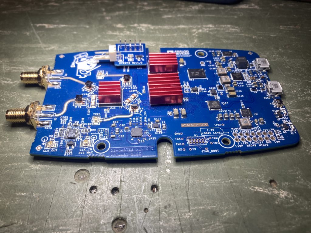
When I ordered my Pluto Charon kit I also purchased the separate PTT module which you can see here (click). This is very easy to install, just make sure you observe good ESD practices when you remove the Pluto from it’s case and handle it on the bench.

Here’s the photo’s of how I installed mine.
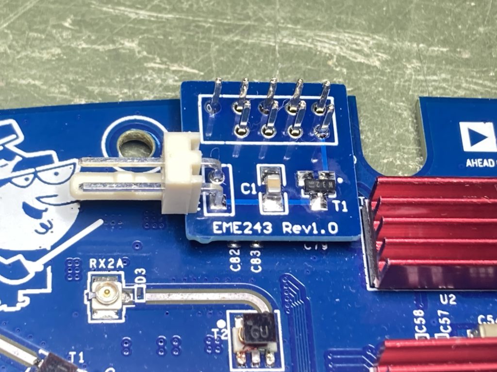
I decided to use a small two pin right angle KK 0.254″ molex connector for the PTT output, as I’d like the capability of unplugging Pluto and Charon boards for service/changes/updates etc.

Now for the hairy scary part of the process. On the Mini-kits website is a URL to some custom firmware written by Evariste F5OEO that can enable a PTT function on a GPIO pin. I was at first a little alarmed by the comment “for the brave”, but it turns out this firmware is part of the PlutoDVB project. You can find later software from 2022 on Christian F5UII’s website (click) and you’ll see some comments about fixing the PTT on the Pluto Rev D boards to work with the latest versions of SDR-Console. I have a Pluto Rev C, which is the same as the Pluto Rev D, so I had no choice but to use this newer firmware and work out what to download.

So after reading most of Christians Website I discovered I had to do two things. Firstly I had to swap from the official ADI Pluto v0.38 firmware to the custom PlutoDVB 3.0.3 firmware. Secondly patch the 3.0.3 firmware to account for the Rev D hardware. This wasn’t obvious where to start.

Below is a summary of the steps I used to swap the firmware.

  • Connected the Pluto to my PC, checked it had presented a removable drive
  • Download the firmware from Christian F5UII”s website, I used the PlutoDVB perseverance firmware 0303 (26.6M)
  • Extracted the pluto.frm from the downloaded zip and stored it on the Pluto removable drive created on my PC (don’t get confused or alarmed by the file name “patch.zip” as this is indeed the entire firmware)
  • Ejected the Pluto and waited for it to finish doing the upgrade and reboot, once done it reconnected to the PC
  • Used a web-browser to point to http://192.168.2.1/index.html, confirmed it presented the “Lets go to PlutoDVB” welcome screen, not the ADI reference material.
  • Then clicked on the “Lets go to PlutoDVB (USB connection)” button which launched into the system setup.php page
  • From the menu across the top, selected “System ” then “Maintenance” where I found the patching and upgrading firmware mechanism.
  • For my hardware (Rev C/D) I needed to download and apply the “Patch for PlutoSDR Rev. D hardware”
  • Applied the patch, saw that within the “Delete Patch” window the updated files were displayed once done
  • Success !

Now I could configure the PlutoDVB firmware to do what I wanted, which in my case was to use SDR-Console. So from the “system” menu at the top I clicked on the “Pass-through” option and hit apply. That should be all I needed to complete.

There is an error message displayed across the top of the screen about a datv text file not being present. If you enter your call-sign in the respective field on the setup page and your name in the DVB provider field, hit “apply settings” and this will create the right file and the error message disappears.

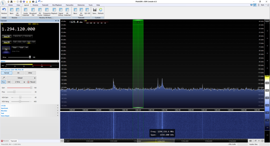
Once all of this was done, I was able to setup and configure SDR-Console and test that the PTT worked with a multi-meter. Below you can see SDR-Console listening on 23cm ready for me to hit the TX button. The Pluto is sitting right up against the PC, so I’m not surprised there are some birdies in the shack, I’ll only panic once the Pluto and Charon and boxed up together.
For my next trick I intend to hook this up to my CRO and see how long before or after the PTT line is asserted does RF appear at the transmit port. However that will have to wait for the next post.

Boxing a Pluto Charon – the Heatsink

For the past couple of weeks I’ve been giving some thought as to how I’d box up the Mini-kits Pluto Charon. As with any problem the first step it to work out how I want to use it.

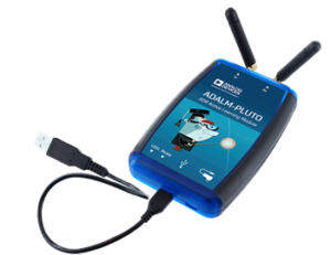
I’d like to be able to use the Pluto Charon both in the field and in the ham shack. The ADLAM Pluto connects to a PC via a micro USB and presents itself as a USB Ethernet device.

Further reading suggests that the ADLAM Pluto USB OTG port can host an external USB-Ethernet adapter or USB-WiFi adapter, making it possible to un-tether the Pluto from a PC or use standard IT infrastructure. In my situation an external Ethernet port is of interest, since I could easily build all of the Mini-Kits Pluto boards into their own enclosure and simply network them together and into the same PC without having to count on multiple USB ports. This again fits with my field and shack mode of operation.

The output power of the Mini-kits Pluto Charon, Pluto Styx and proposed Pluto Nix kit is in the region of one to two watts. This is more than enough transmit power to jump from hilltop to hilltop over quite a path with some antenna gain and short cables. If however you want to lift the antennas up to the top of mast, external in-line amplifiers up behind the antennas would be required to keep losses under control. If the external amplifiers also included a separate mast head amplifier, then losses of up to 6-8dB at any of these microwave frequencies could be accommodated without significantly impacting performance. I’ll be exploring this further once the first Pluto Charon kit is completed.

So, the first step of course is to get the Pluto Charon kit operational, to do that I needed to test it. The kit came with a small 40x40mm heatsink that I could attach to dissipate the heat from the final amplifier IC1. I mulled this over for a while before deciding I’d prefer to put a much larger heatsink on the top of a die cast box and mount the Pluto Charon to that. A good example of what I’m thinking is how I built my Rubidium reference (here). My main reasoning is I’d like to stabilise the heat within the die cast box so the Pluto does not need to work so hard on keeping the frequency stable. Did I mention the Rubidium reference, one would say this started these shenanigans.

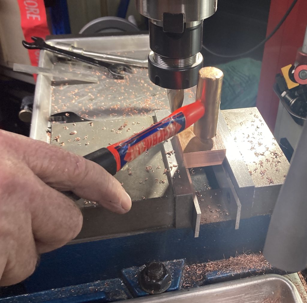
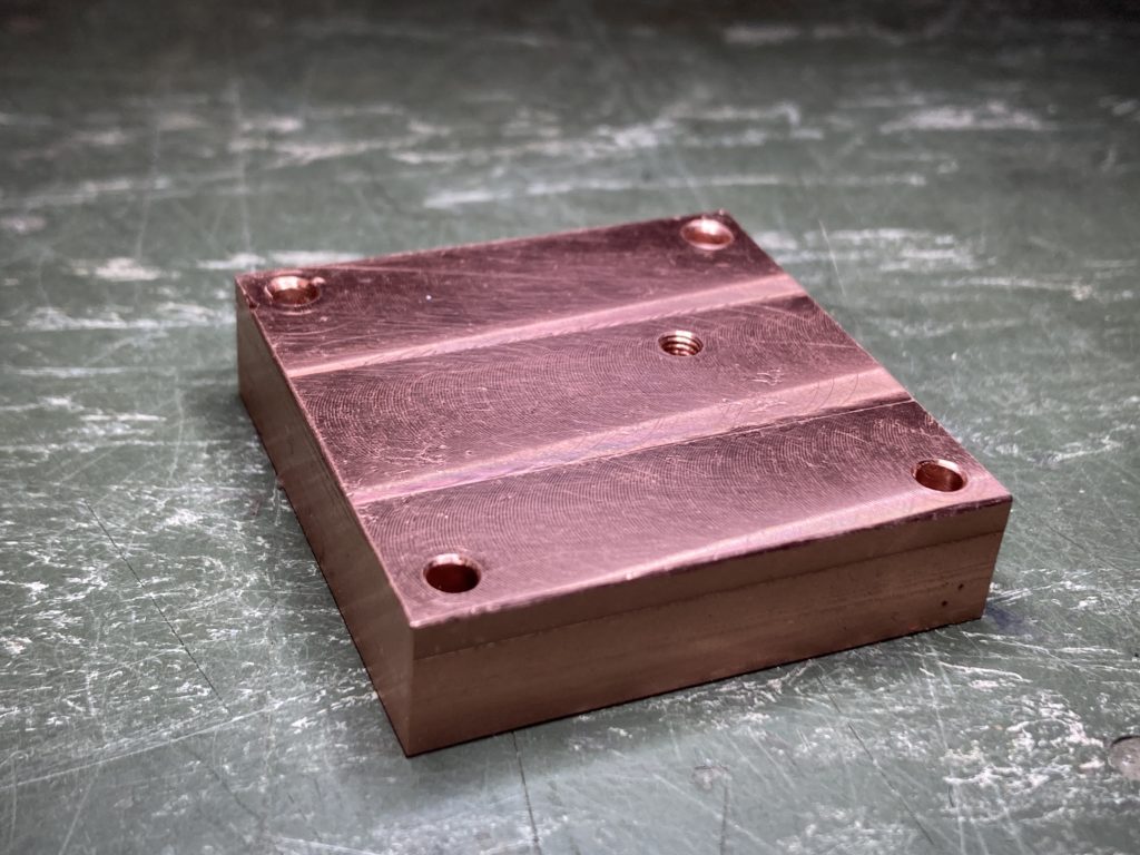
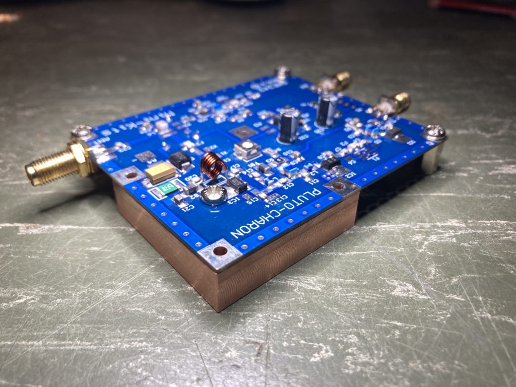
To get the heat out of the Pluto Charon final amplifier the layout dictated a small copper block to be made. There are components on the top and bottom of this board, so one needs to pay attention to clearances etc. So it was off to see a good friend with a lathe ;thanks Peter it was a fun afternoon and some good machining Zen !

It is no coincidence that the copper block is 10mm thick, this is perfect for three 10mm hexagonal spacers to be placed under the remaining three sides of the PCB for support.

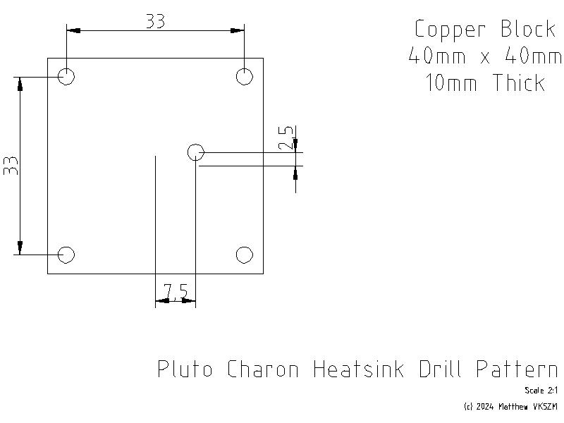
The hole in the middle of the copper block is what transfers the heat from IC1, so this was tapped to accept a M3 hole. The PCB had a plated 2.5mm hole and was reamed out slightly to accept the larger M3 screw. The M3 screw used was tin plated copper, not tin plated steel/stainless which is a poor conductor of heat.

The remaining four holes in the PCB that hold the heatsink were left M2.5 and the holes through the copper block drilled 3mm for clearance. When this is attached to the heatsink, four M2.5 x16mm screws through these holes in the heatsink, washers and split washers will be used to sandwich the assembly and keep everything held tight.

So I don’t forget and for anyone following along at home I’ve included the drill pattern. This was the only information conspicuously absent from the assembly instructions. This drawing is drawn from the top of the PCB looking down. The hole in the middle of the heatsink is referenced from the center of the copper block. For some reason I can’t get LibreCAD to show a mark for the origin yet. I hate having to measure PCB’s to get hole locations, a combination of transfer punches, vernier calipers and gauge pins were used to establish and check that these locations were close enough.

Now it’s time to carry on with the Testing and Alignment of the Pluto Charon !

So after two years ?

For quite some time I’ve been promising my eldest son his own bedroom. However like everything, this is somewhat complicated and has taken far longer than expected. To make this happen, I’ve had to make more shelving in the shed, move stuff stored in the garage out into the shed, clean out the garage and move my office, which was in the 3rd bedroom of the house out into the garage soon to become my new man-cave. I’ve felt like I’ve been playing musical chairs with storage boxes for quite some time. Then there is the time required to renovate said 3rd bedroom back into a teenagers retreat, so much work, so many weekends, I still hate painting.

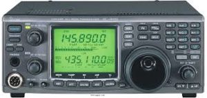
However, while moving things out of the office and into the new man-cave I rediscovered the Pluto Charon kit, languishing in a forgotten project box. My original plan was to use this kit as my 23cm home station, however during the above renovations a member of my radio club offered me a pristine Icom IC-910H with 23cm module which I couldn’t refuse. Needless to say the Pluto Charon priority and urgency was pushed back somewhat.

Fast forward two years and having rediscovering this kit, along with seeing the new 12cm Pluto Styx kit available (click) and a teaser for the 6cm Pluto Nix, well it was time to finish it and continue working my way up through the microwave bands.

BGU8051 are small

This kit requires the usual SMD microwave construction techniques, so fine solder a good iron, a steady hand and optical magnification is an absolute must. The Mini-kits instructions and support page are as usual first class. However one should heed the warning on the website ordering page that “this kit is not for beginners and requires very experienced soldering skills”.

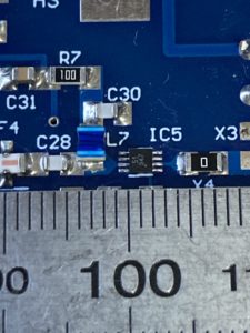
I generally found the majority of the kit straightforward, until I got to IC5 which is a BGU8051 preamp from NXP. You should check out it’s specs on the NXP website. This is one of those “looks big on the computer screen” kind of parts that even designers get caught out with when ordering their first samples. I’ve included a photo, along with a strategically placed steel ruler for scale. That IC is tiny… really tiny !!!

At just two by two by three-quarters of a millimeter with eight pins, it was clear that this was not going to be soldered by any ordinary soldering iron. Thankfully I have a hot-air rework station, so I manually pasted the board with an I-Extruder, used plenty of flux and re-flow soldered the device to the board. Since inductor L7, capacitor C30 and resistor X3 were so close, I chose to leave these off until I had soldered IC5 to give me room and ensure the hot air did not cause unnecessary stress to adjacent components, YMMV. I also typically use a T3 solder paste for the majority of my kit building, but for this board I resorted to using T4 since you could nearly count the number of solder balls dispensed onto each pad of IC5. However I’m happy with the result and with the right tools this kit can be assembled at home. There are many YouTube tutorials on how to solder with hot-air worth watching as well.

Once I had the kit soldered together I then turned my attention to how I was going to put it in a box and begin to test it. However that is for the next post !