
I recently found myself at the very limits of what you can ask an Arduino Uno to do, both in terms of flash and speed. I’ve used Atmel AVR processors for nearly 20 years so I know them and their foibles very well.
At work a while back we started using various STM32 processors and that has been somewhat enjoyable, I now like throwing floats around instead of having to resort to fixed point maths and excel for algorithm development. I’d heard that you could run up the Arduino framework on the STM32 platforms so was keen to try it.
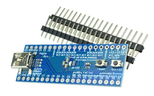
So I initially went looking for a well supported board and simply struggled to find one. It seemed that this space had come and gone rather rapidly. Further research showed why, the Chinese clones has effectively decimated this market due to price. I was still keen to give it ago so placed an order for two Maple Mini boards with the STM32F103CBT6 processors on them off eBay for the princely sum of A$20 with free freight. Little wonder everyone abandoned ship in mid 2016.
A big thanks has to go to Leaflabs since they have left all of the circuits, boot-loaders & design files in a GitHub repository here (click).
So what did we have to do to get these working ? It wasn’t as trivial as the Arduino Uno that is for certain.
The first step was to get Windows 7 drivers (yes I know it runs out next year) for the Maple Mini, I found some here (click). I basically hit the green button marked “Clone or Download”, saved the file on my local machine. Extracted the files from the archive to a temp directory, then via the System Manager clicked on the “Maple 003” device that appears, told it I wanted to update the drivers from a specific location then pointed it at the temp directory I’d stored the files in previously. It figured it out and installed the ones I needed. What I found amusing is it then appeared under a category called “Atmel Devices” since I’d installed tools based on libdfu for these devices once upon a time ago. YMMV.
Once I had drivers installed I could then fire up PlatformIO in the VSCode editor and attempt to create a new project. I selected the board type “Maple Mini Original” and “Arduino” for the platform and let it do its business. Unfortunately the processor I have and the one on the original maple mini are different, so I had to change a few things in the platformio.ini file; my config is below. This config is based on a PlatformIO blog post written by Vortex314, can’t thank them enough for sharing this information (click).
[env:maple_mini_origin]
platform = ststm32
board = maple_mini_origin
framework = arduino
board_build.mcu = stm32f103cbt6
board_build.f_cpu = 72000000L
build_flags =
    -D USBD_USE_CDC
    -D PIO_FRAMEWORK_ARDUINO_ENABLE_CDC
    -D PIO_FRAMEWORK_ARDUINO_USB_FULLMODE
    -D USBCON
    -D USBD_VID=0x0483
    -D USB_MANUFACTURER="Unknown"
    -D USB_PRODUCT="\"BLUEPILL_F103C8\""
    -D HAL_PCD_MODULE_ENABLED
So what is so special? Firstly there are separate board_build definitions to set the processor and speed for the board. Thankfully the cores between the original board and my Chinese clone are similar enough for this to work. Secondly there’s a heap of additional build flags that will build in a USB serial port. So if you’re used to the USB serial to debug your code this will still work. You can find out a little more about why this is necessary on Roger Clark’s website here (click).
It is interesting that the boot-loader contains only DFU code and that the application needs to have the USB serial built in separately. In the above configuration you may notice that the VID is 0x0483 which is by design, this means the Communications Device Class (CDC) will trigger the ST Serial drivers on a Windows installation if you have them installed. If you don’t you can find them here (click).
So from within the PlatformIO environment we can write our code and build for our target. Here’s my very simple test program that flashes the onboard LED (pin 33) and will send some test data to the USB serial port.
#include <Arduino.h>

void setup()
{
  // put your setup code here, to run once:
  pinMode( 33, OUTPUT );
  Serial.begin(115200);

}

void loop()
{
  static int i = 0;

  // put your main code here, to run repeatedly:
  digitalWrite( 33, HIGH );
  delay(500);
  digitalWrite( 33, LOW );
  delay(500);

  Serial.print("Test #");
  Serial.println(i++,DEC);
}
So the last comment I need to make is in the programming of the device. When you hit the upload button from within PlatformIO you’ll see OpenOCD start and then pause with the comment “Searching for DFU device [LEAF:0003]” and if you wait long enough a subsequent message flashes by reading “Couldn’t find the DFU device: [LEAD:0003]” and nothing appears to happen.
Initially I thought my board was dead when it dawned on me… The Arduino uses a separate ATmega8U2 that is capable of resetting the target ATMega328 under software control, the STM32F103Cx is using the internal USB port and does not have this reset function (*face palm*). So when we start the program cycle we need to wait for the “Searching for DFU device” to appear and then manually reset our target to force the boot-loader into DFU mode momentarily where it is then caught and updated. Once done the process carries on as expected and you find you haven’t bricked your device.
Happy programming !