
 Many stackmatch designs use a toroid core, but I’ve decided to instead investigate using a multi-aperture “binocular” core.
There are not many manufacturers of large-ish binocular cores that can take the full VK HF limit of 400W PEP, let alone a full kilowasp amplifier !
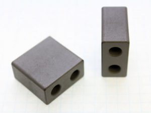
So to start with I’ve chosen two well known binocular cores that you can obtain from various online suppliers;
- Amidon BN-61-002
- Fair Rite 2861010002
Both are the equivalent of each other in terms of price, size and material. Both are made from Type 61 NiZn Ferrite material with a ui of approximately 125. This material has good low loss properties and is essentially what others have used for their toroid designs. It seems like a good place to start.
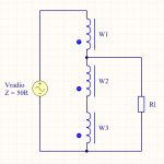 The transformer is wound the same way as if on a toroid, so take three wires, twist them together (battery drill helps) and wind the desired number of turns through the holes. It seems sensible to start with a full core and take turns off if I achieved too much inductance. Both of these cores hold ~4 turns of trifiliar wound 20AWG silver plated PTFE wire, it might add the last turn is hard to do. All that is left is to series up the windings and tap at the appropriate positions, the schematic is to the right.
To make my measurements I decided to use a variable resistor (R1) to check the effect of load change on the transformer. I had also seen some designs using a small amount of shunt C across the output to neutralise the output leakage inductance as well, so I placed a variable cap across the variable resistor when needed.
To make these measurements I’m fortunate to have a Spectrum Analyser with tracking generator and a suitable Return Loss Bridge. The return loss bridge has a directivity of > 45dB at HF. This means I can see how much energy is being transferred to the load resistor (R1), any RF energy that is being reflected back to the spectrum analyser is therefore wasted, so in all of the screen captures below the lower the Return Loss the better !
You can see the experimental setup in the image below and my initial measurement on the kitchen table…
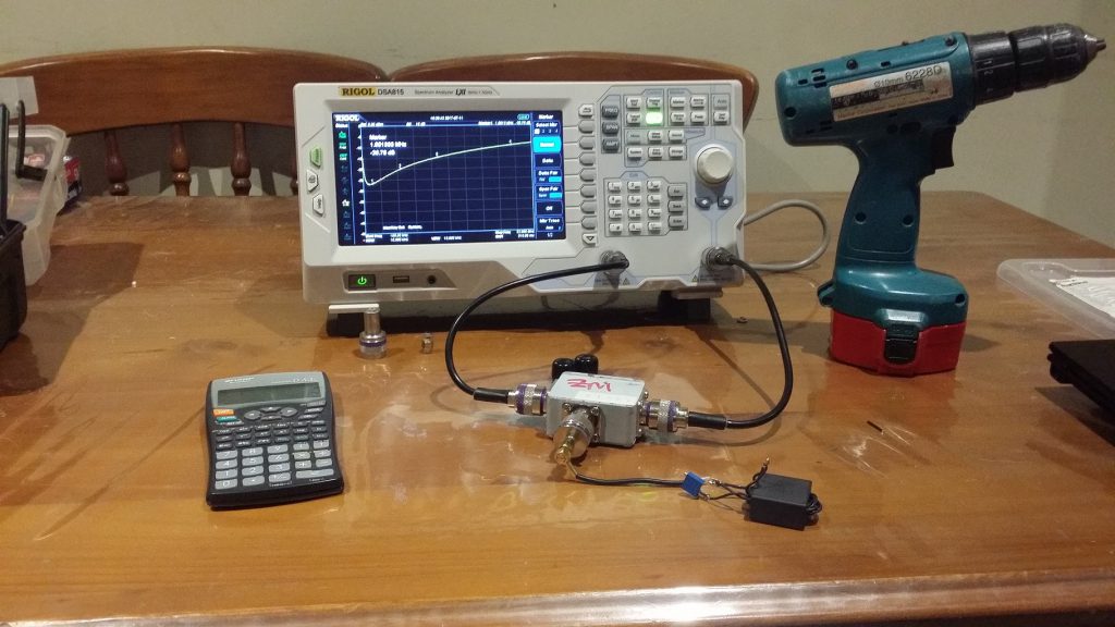
I’d start these measurements by adjusting R1 until I achieved the lowest Return Loss and then remove the resistor temporarily and measure it separately with a 4-digit ohmmeter. I wanted to check that I was close to 22.2 ohms in all cases. With such a low resistance don’t forget to deduct the resistance of the multimeter leads.
Once I had confirmed the impedance transformation was correct I would then tack the trimmer cap across R1 and start with it completely un-meshed (min C). The cap on the secondary side of our transformer will assist in “tuning” out the output reactance (Xs) of the transformer a little and improving the return loss at the upper end of our plot.
However there is a null that will occur at the low end of VHF that you need to be wary of as it can be unstable, you can if you have enough capacitance bring it into HF spectrum which is not advisable. You will easily see the point where I’ve added too much in the sequence below. What you’re looking for is just enough turns to give you the broadest match possible with the smallest value of C across it’s output.
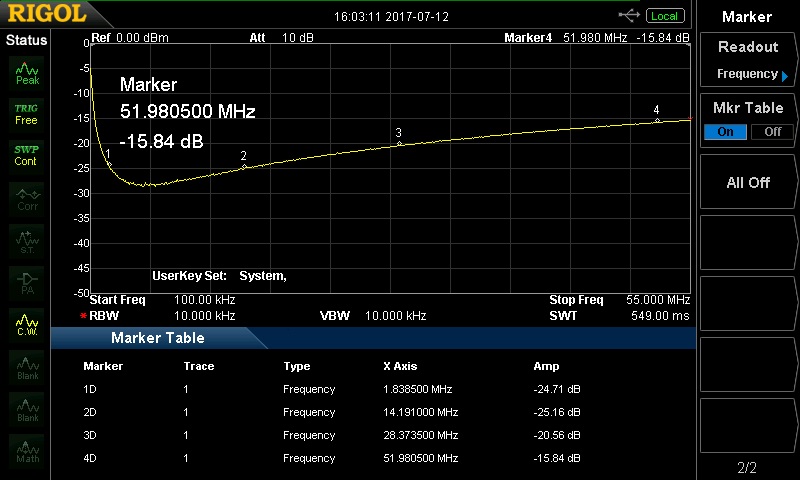
Here’s a sequence of plots showning what happens as you increase C from min (5p) to too much (120p). This was with 3 turns wound through the core, R1 approx 22.3 ohms;
So in the above sequence you can see what the effect that the capacitance has across the output. As we keep adding capacitance the return loss kept getting better and better before the null appears. The ideal compromise was somewhere between 65p-80p.
What you can also do is widen out the frequency from 1-200MHz and watch what effect any nulls will have on the response. It also pays to vary the load (R1) and see what happens as the load decreases below and above the desired match. I found that as the output impedance goes up the null has a much more prominent effect as the load is varied.
So starting at 4 turns I checked the impedance ratio and then wen’t looking for the best compromise in terms of response, stability and lowest capacitance. Below are the three best candidates that I found;
So as we reduce the turns (inductance!) we see the return loss decrease at the low end, but we also see the required capacitance to flatten out the upper end also reduce. Based on these measurements the best compromise I found for this transformer is 2T C=30p. Ideally a return loss less than -20dB is a good target to aim for, I’ll let the reader work out what the equivalent VSWR is for this RL value (hint: it’s low, for additional points also take a look at a RL of -10dB for reference !).
Now to check that this is stable I’ve included a plot that is much wider in terms of checking the VHF region for signs of that null we wish to avoid. Hmm, this combination is potentially usable up to 6m, now there’s an idea for another day.
Sweet no signs of the null being anywhere close to the MF/HF bands I want to operate over.
Now the ultimate test is to make two of these transformers, place them back to back into a 50 ohm load then measure the insertion loss. That will give me some idea on what sort of loss this transformer will have an ultimate how hot it will get when I attempt to pass 120W CW/FM or 400W pep of SSB.
More to come.