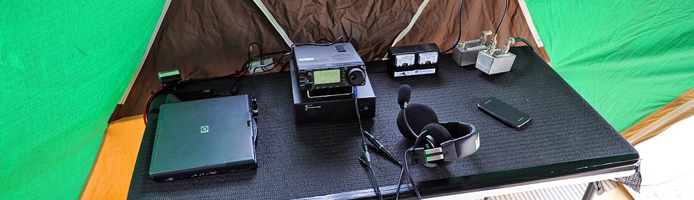
In October each year I join my local radio club AREG and participate in the Oceania DX (OCDX) contest. For the past few years I’ve been the band captain for the 15m/10m station. We started in 2014 with just an Icom IC-706mk2 and 2 element broadband Hexbeam, but this quickly morphed into a complete Elecraft K-line, Amplifier, SDR’s, filters and Spiderbeam on a 8m pump up mast; as a portable station.
So to take our station yet another step forward we need to add additional antennas like mono-band verticals to take advantage of lower propagation angles. Here in VK we are along way from anywhere, so the majority of our propagation on most bands is below 20 degrees. However before you can take advantage of these additional antennas you need to switch between them.
Trolling the internet for inspiration we discovered the 3 to 1 Broadband Stackmatch. This is a simple 3 port antenna switch that can individually switch each antenna to the radio, but it can also be used to parallel up any two or all three antennas ports together.
It exploits the fact that two 50+j0 ohm antennas in parallel is 25+j0 ohms and three in parallel just shy of 16.7+j0 ohms. So by inserting a transformer with a fixed impedance matching ratio we can bring the parallel antennas effective impedance back up close enough for many amplifiers/transceivers not to care about the minor mismatch. So that is deviously clever and simple.
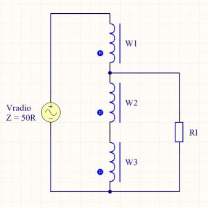
The equivalent circuit of a stackmatch transformer is shown to the right, you’ll see it drawn many different ways but I find it easier to understand when drawn as an autotransformer.
Accordingly the maths says;
n = Np / Ns
Z’ = (n)^2 x Zload
So lets see what happens;
Np = 3, Ns = 2, n = 3/2 = 1.5
So with two antennas in parallel;
Z’ = (1.5)^2 x 25 = ~65.3 ohms
With three antennas in parallel;
Z’ = (1.5)^2 x 16.7 = ~37.6 ohms
This small impedance mismatch (~14 ohms) either side of 50 ohms will not cause many radios much difficultly. It does however tell us that we must ensure that our antennas are resonant (50+j0) since we have ignored the imaginary impedance for simplicity. What is also not explained is you need to keep the feedlines to each antenna from the stackmatch as close to the same length as you can or there be more trouble with impedance transformations.
There are plenty of designs on the internet and products available from suppliers but their cost are quite simply prohibitive, especially if you want 6 or more of these units to achieve your desired switching arrangement (*gasp*) at a contest.
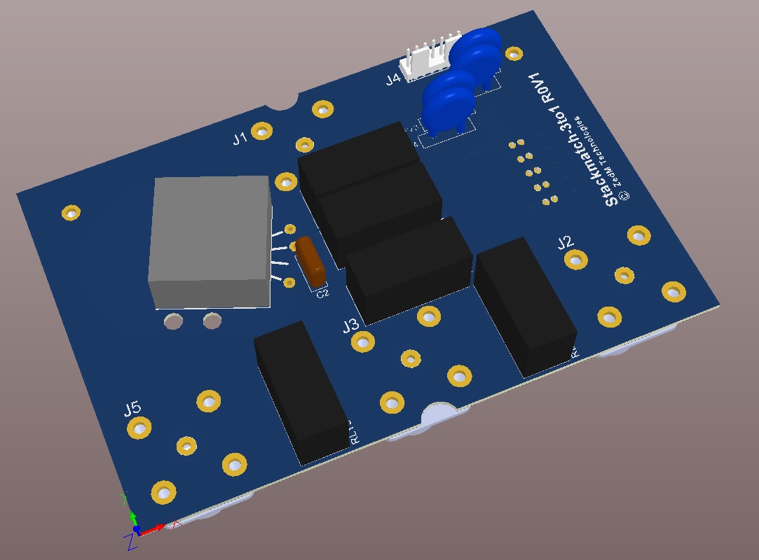
So here starts yet another project to design and build my own low cost 3 to 1 Stackmatch. It certainly has not taken long to come up with a workable 3D model. It kind of helps that I design products like this every day as an Design Engineer. I’ve also learnt a trick or two about lowering cost in my time.
However in talking about this project over a coffee with an old work colleague/Boss he reminded me about the perils of using Toroid cores for broadband transformers. He suggested I should instead use a multi-aperture “binocular” core or “pig nose” core as I seen them listed on eBay (LOL). These binocular cores also have the added advantage of being smaller than a FT240-61 toroid core that everyone seems fond of. You can see the grey block in the picture below that represents this core, it’s tiny compared to the equivalent toroid.
So that begs the question, just how good are they ? Well there is nothing like buying a core and winding one to find out (click).