Motorola CPS on Windows 10/11

It is no secret that Motorola CPS software does not like to run on modern operating systems. I still have a number of UHF Motorola MTS2000 handhelds which once given new batteries have proven themselves useful time and time again.

However my trusty old Windows XP laptop, with a real serial port fried its motherboard recently never to boot again. My immediate thought was “yikes what do I use now to program these Motorola radios” ?

So rather than go looking for further ancient hardware I started experimenting if Motorola CPS would run on a Windows 10 64-bit platform. I’ll spare you the gory details, but not amount of compatibility mode twiddling or research would result in a working system. There is something fundamental in the RS232 32-bit sub-system within the CPS software that prevents this from ever working. I could not get the CPS software to “read device” instead receiving a timeout. Grrrr….

So the only alternative was to experiment with an older version of Windows in a virtual machine and passing through a serial port. I remember when Windows 7 was first released Microsoft released a version of Windows XP that would run within Microsoft Virtual PC. The Motorola CPS software is from around the same time, so it was an ideal candidate to try. Turns out this was easier than I expected.

Setup Windows XP Virtual Machine

I found the following setup guide very useful from Help Desk Geek website (click). The download link from the Microsoft site has disappeared, but the alternative link from the CNET site was working at the time of this post.

I followed this guide closely, there are a few steps you needed to pay attention too but otherwise this went smoothly. I’m currently using a Windows 10 host and the only trouble I had was with the mouse, where I could not control the mouse within the Guest correctly, but you can temporarily disable the VirtualBox “mouse integration” feature to get around this until the VirtualBox Guest Additions are installed. Once the Guest additions were installed, everything worked as expected.

Activating Windows XP in 2022

The next challenge is since Windows XP support ended there is no way to “activate” this vanilla of windows any more which is right painful. One work around is to snapshot the VM and rollback each time you wish to use it, I wasn’t a fan. So thankfully the “Adventures in Nostalgia” YouTube channel had a video that shows how a regedit method to work around this problem, don’t forget to leave a like.

Serial Port Pass Through

Now I’m lucky that my Gen-3 I7 desktop machine has a real serial port on the motherboard. This was one of the very last Intel made motherboards with the legacy IO chipset, so not only do I have a serial port it has a parallel port too.

To allow Windows XP access to the host serial port, one just needs to configure the hardware pass through. Within the VirtualBox settings there is a separate “Serial Port” tab that simply requires mapping between the guest and host systems.

As you can see I’ve simply mapped COM1 on the guest to COM1 on the host, simples !

Copying Motorola CPS into Windows XP

So for the grand finale we can install the Motorola CPS software within Windows XP. How one gets the software installed can be done a few different ways.

I decided to use the VirtualBox shared folders mechanism. With the guest additions installed I found once I’d configured the shared folders they were automatically mapped as a network drive the next time I restarted the Windows XP guest. It was a simple matter to then double click the executable and install.

There were a few websites with rough instructions, but I found after watching the following YouTube video from Peter Downie I was able to get it working in short order;

The other method I’ve used to pass software through to a guest is to use a USB thumb drive. Copy the files from the host to the USB, pass the USB through to the guest, move the files and eject to pass it back. Both methods work just as well as each other.

The Proof is in the Pudding

So once you can copy the relevant files into the VM, then it’s a simple matter to install and run the Motorola CPS software. Then simply configure it to talk to the serial port you’ve passed through which is COM1 in my case, then try to read a physical radio. Please note that Motorola CPS software is licensed and cost real $$$ to purchase, please do not request copies of said software fro me as refusal often offends.

You will know you’ve got it right when you hear the radio beep, it says PRGM on the radio display and you are greeted with the contents of your code plug.

I was certainly relieved to be greeted with the screen shown above, make my changes and write the config back to the radio. I’m once again in business. I hope that other users of older Motorola CPS software find this useful.

Display a PNG Image on small 128×128 OLED LCD

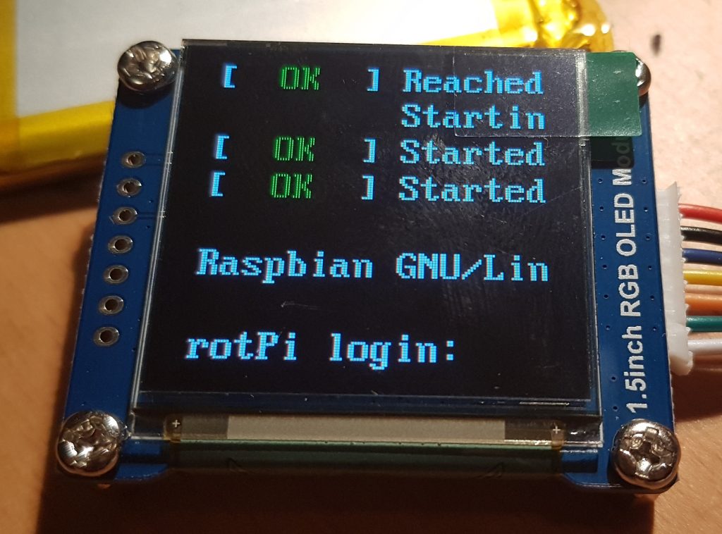
Now that my small OLED display automatically loads the device drivers on boot, it was time to see if I could display an image on my new frame buffer device.

To start with I went looking for a very basic graphics library that would allow me to experiment on frame buffer devices. There is certainly no shortage of libraries to choose from. The library that I settled on was the “Lightweight C 2D graphics API agnostic library with parallelism support” written by grz0zrg. It had both PNG and JPG routines that could output to a simple frame buffer device, being written in C was also a winner.

Flicking through the various examples the quickstart.c file seemed to have nearly everything I needed to display a PNG file on my OLED. Not so long ago a fellow AREG club member shot me some icon files for our club website; one of these icons was 512×512 pixels in size which made it an excellent candidate for shrinking to 128×128 pixels and using it on my OLED.

Downloading the library was as easy as;

$ cd ~
$ git clone https://github.com/grz0zrg/fbg

If you don’t have git installed use the relevant apt-get command. The example files can then be found in the following directory;

$ cd ~/fbg/examples 

I then copied the quickstart.c file and hacked on it a little, modifying it like so;

#include <sys/stat.h>
#include <stdio.h>
#include <signal.h>
#include "fbgraphics.h"

int file_exists( const char* filename )
{
    //define file handle
    FILE *file;

    //attempt to open file read only
    if( (file = fopen(filename, "r")) )
    {
        fclose(file);    // release file handle
        return 1;        // tell someone we found it
    }
    else
    {
        return 0;         //no one home
    }
}

int main(int argc, char* argv[])
{
    const char* framebuffer_name = "/dev/fb1";
    const char* logo_filename = "logo.png";

    //check we have a framebuffer to talk to
    struct _fbg *fbg = fbg_setup( (char *)framebuffer_name, 0);
    if (fbg == NULL)
    {
        return -1;
    }

    // make sure logo file exists
    if( !file_exists( logo_filename ))
    {
        printf("File not found: %s\r\n",logo_filename);
        return -2;
    }

    //draw something on the display
    struct _fbg_img *logo = fbg_loadPNG(fbg, "logo.png");
    fbg_clear(fbg, 0);
    fbg_image(fbg, logo, 0, 0);
    fbg_flip(fbg);
    fbg_draw(fbg);

    //release memory
    fbg_freeImage(logo);
    fbg_close(fbg);

    return 0;
}

Which was built with the following command line from within the examples directory;

gcc ../src/lodepng/lodepng.c ../src/nanojpeg/nanojpeg.c ../src/fbgraphics.c display_logo.c -I ../src/ -I. -std=c11 -pedantic -D_GNU_SOURCE -D_POSIX_SOURCE -Wno-unused-value -Wno-unknown-pragmas -O2 -Wall -lm -o display_logo

Hacking upon the Makefile is also not that difficult, I simply added the relevant lines the SRC and OUT sections, then copied the quickstart section and renamed display_logo. There is lots of information about on how to do this on the internet so I’ll not repeat it again unnecessarily.

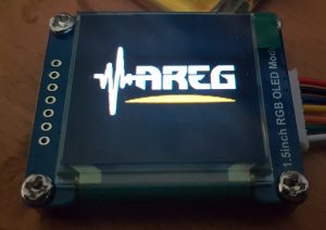
All I had to do then was place my 128×128 PNG file alongside the display_logo executable (renamed logo.png) and run it… wallah ! I was greeted by the AREG logo on my small OLED display in all of its 128×128 pixel glory; see the image at the top of this post.

So the next trick is to move this to the boot process… So by the looks the plymouth package might be the go, only one way to find out.

Starting a fbtft_device on Boot

After having woken up my small 128×128 OLED display I was wondering how to get it to start automatically each time my rPi booted rather than having to log in and run the commands manually.

It turns out this is rather easy and just required me to edit two files. I’m also glad that these Waveshare OLED displays are effectively compatible with the Freetronics OLED 128×128 graphics display. A big thanks to the Freetronics team for making this driver available for SED1351 chip sets.

So I created the following file with my favourite editor (as root) /etc/modprobe.d/fbtft.conf with the following contents;

options fbtft_device name=freetronicsoled128

What this effectively does is tell the system how to configure the fbtft_device as it boots, much like if we started it with modprobe from the command line i.e used the following command;

sudo modprobe fbtft_device name=freetronicsoled128

So now the system knows how to configure the driver, we need to tell modprobe to load it by placing an entry in the /etc/modules file. So using your favourite editor (as root) edit /etc/modprobe and append the last two lines.

# /etc/modules: kernel modules to load at boot time.
#
# This file contains the names of kernel modules that should be loaded
# at boot time, one per line. Lines beginning with "#" are ignored.

i2c-dev
spi-bcm2835
fbtft_device

It appears that the SPI bus is a little slow to load if it’s called as a dependency of fbtft_device, which is a classic chicken and egg driver problem. So by starting it manually we make sure it’s available by the time the fbtft driver tries to do anything.

The i2c-dev entry in the same file fires up the i2c bus and was already pre-configured in my system by raspi-config way back when. I’m using it in my project, YMMV. All that is left to do is test it, so reboot and login and run the following command;

$dmesg | grep graphics

We should see something like the following;

[6.128978] graphics fb1: fb_ssd1351 frame buffer, 128x128, 32 KiB video memory, 4 KiB buffer memory, fps=20, spi0.0 at 20 MHz

That tells us that the little OLED display has registered as /dev/fb1 and that it’s ready to go. You can use the con2fbmap trick in my last post to test it’s working.

Now to work out how to get it to throw up an image on boot…

Maple Mini’s & a STM32F103CBT6

I recently found myself at the very limits of what you can ask an Arduino Uno to do, both in terms of flash and speed. I’ve used Atmel AVR processors for nearly 20 years so I know them and their foibles very well.

At work a while back we started using various STM32 processors and that has been somewhat enjoyable, I now like throwing floats around instead of having to resort to fixed point maths and excel for algorithm development. I’d heard that you could run up the Arduino framework on the STM32 platforms so was keen to try it.

So I initially went looking for a well supported board and simply struggled to find one. It seemed that this space had come and gone rather rapidly. Further research showed why, the Chinese clones has effectively decimated this market due to price. I was still keen to give it ago so placed an order for two Maple Mini boards with the STM32F103CBT6 processors on them off eBay for the princely sum of A$20 with free freight. Little wonder everyone abandoned ship in mid 2016.

A big thanks has to go to Leaflabs since they have left all of the circuits, boot-loaders & design files in a GitHub repository here (click).

So what did we have to do to get these working ? It wasn’t as trivial as the Arduino Uno that is for certain.

The first step was to get Windows 7 drivers (yes I know it runs out next year) for the Maple Mini, I found some here (click). I basically hit the green button marked “Clone or Download”, saved the file on my local machine. Extracted the files from the archive to a temp directory, then via the System Manager clicked on the “Maple 003” device that appears, told it I wanted to update the drivers from a specific location then pointed it at the temp directory I’d stored the files in previously. It figured it out and installed the ones I needed. What I found amusing is it then appeared under a category called “Atmel Devices” since I’d installed tools based on libdfu for these devices once upon a time ago. YMMV.

Once I had drivers installed I could then fire up PlatformIO in the VSCode editor and attempt to create a new project. I selected the board type “Maple Mini Original” and “Arduino” for the platform and let it do its business. Unfortunately the processor I have and the one on the original maple mini are different, so I had to change a few things in the platformio.ini file; my config is below. This config is based on a PlatformIO blog post written by Vortex314, can’t thank them enough for sharing this information (click).

[env:maple_mini_origin]
platform = ststm32
board = maple_mini_origin
framework = arduino
board_build.mcu = stm32f103cbt6
board_build.f_cpu = 72000000L
build_flags = 
    -D USBD_USE_CDC
    -D PIO_FRAMEWORK_ARDUINO_ENABLE_CDC
    -D PIO_FRAMEWORK_ARDUINO_USB_FULLMODE
    -D USBCON
    -D USBD_VID=0x0483
    -D USB_MANUFACTURER="Unknown"
    -D USB_PRODUCT="\"BLUEPILL_F103C8\""
    -D HAL_PCD_MODULE_ENABLED

So what is so special? Firstly there are separate board_build definitions to set the processor and speed for the board. Thankfully the cores between the original board and my Chinese clone are similar enough for this to work. Secondly there’s a heap of additional build flags that will build in a USB serial port. So if you’re used to the USB serial to debug your code this will still work. You can find out a little more about why this is necessary on Roger Clark’s website here (click).

It is interesting that the boot-loader contains only DFU code and that the application needs to have the USB serial built in separately. In the above configuration you may notice that the VID is 0x0483 which is by design, this means the Communications Device Class (CDC) will trigger the ST Serial drivers on a Windows installation if you have them installed. If you don’t you can find them here (click).

So from within the PlatformIO environment we can write our code and build for our target. Here’s my very simple test program that flashes the onboard LED (pin 33) and will send some test data to the USB serial port.

#include <Arduino.h>

void setup() 
{
  // put your setup code here, to run once:
  pinMode( 33, OUTPUT );
  Serial.begin(115200);
  
}

void loop() 
{
  static int i = 0;
  
  // put your main code here, to run repeatedly:
  digitalWrite( 33, HIGH );
  delay(500);
  digitalWrite( 33, LOW );
  delay(500);

  Serial.print("Test #");
  Serial.println(i++,DEC);
}

So the last comment I need to make is in the programming of the device. When you hit the upload button from within PlatformIO you’ll see OpenOCD start and then pause with the comment “Searching for DFU device [LEAF:0003]” and if you wait long enough a subsequent message flashes by reading “Couldn’t find the DFU device: [LEAD:0003]” and nothing appears to happen.

Initially I thought my board was dead when it dawned on me… The Arduino uses a separate ATmega8U2 that is capable of resetting the target ATMega328 under software control, the STM32F103Cx is using the internal USB port and does not have this reset function (*face palm*). So when we start the program cycle we need to wait for the “Searching for DFU device” to appear and then manually reset our target to force the boot-loader into DFU mode momentarily where it is then caught and updated. Once done the process carries on as expected and you find you haven’t bricked your device.

Happy programming !

Small OLED Display on a rPi

Recently I was searching for a small graphic display that I could connect to a Raspberry Pi and fit within a Phoenix DIN enclosure I wanted to use.

There isn’t much space in the front of the enclosure I wanted to use, but a small 128×128 OLED colour display seemed it might fit.

Trawling through eBay I found what I thought to be a suitable unit and simply placed an order. There was very little information on the eBay site to tell me which display I had purchased so I just waited. When the display arrived it turned out to be a Waveshare SKU:14747 with the SED1351 controller.

A little searching around the web and I found an excellent tutorial written by the Freetronics Team for their 128×128 OLED display. It turns out our displays share the same SED1351 controller, so it was the logical place to start with my small display.

First task was to map the OLED pins to my rPi 3B+ 40-pin GPIO connector. On the rear of the display the pins and their desired function were clearly marked, so I mapped the pins like so;

OLED    | rPi      (pin)
--------+----------------
+5      | 5V       (1)
GND     | 0V       (3)
MOSI    | SPI_MOSI (19)
SCK     | SPI_SCK  (23)
CS      | SPI_CE0  (24)
DC      | GPIO25   (22)
RST     | GPIO24   (18)

I have also included the rPi pin numbers I used, make sure you plug the display into the right pins if in doubt RTFM. Once it was wired I ran the following commands to make sure the rPi was absolutely up to date;

sudo apt-get update
sudo apt-get dist-upgrade
sudo reboot

The latest version of Raspbian Lite I was using (Buster) came with the fbtft frame buffer drivers already installed, so these steps were unnecessary. Since this Raspbian installation was fairly recent I decided that I didn’t need to update the rPi firmware using the rpi-update command like in other tutorials; YMMV.

I had already enabled the SPI bus on my Pi when I was coming to grips with the I2C bus. I found the tutorial at Sparkfun a really good reference and easy to follow. To create the frame buffer for the OLED device I ran the following command;

sudo modprove fbtft_device name=freetronicsoled128
dmesg | tail -20

Fingers crossed we see the following output in our terminal;

fbtft: module is from the staging directory, the quality is unknown, you have been warned.
fbtft_device: module is from the staging directory, the quality is unknown, you have been warned.
spidev spi0.0: spidev spi0.0 125000kHz 8 bits mode=0x00
spidev spi0.1: spidev spi0.1 125000kHz 8 bits mode=0x00
bcm2708_fb soc:fb: soc:fb id=-1 pdata? no
spidev spi0.0: Deleting spi0.0
fbtft_device: GPIOS used by 'freetronicsoled128':
fbtft_device: 'reset' = GPIO24
fbtft_device: 'dc' = GPIO25
spidev spi0.1: spidev spi0.1 125000kHz 8 bits mode=0x00
spi spi0.0: fb_ssd1351 spi0.0 20000kHz 8 bits mode=0x00
fb_ssd1351: module is from the staging directory, the quality is unknown, you have been warned.
graphics fb1: fb_ssd1351 frame buffer, 128x128, 32 KiB video memory, 4 KiB buffer memory, fps=20, spi0.0 at 20 MHz

The output here shows us that the SPI bus is OK and that we now have a frame buffer /dev/fb1 that is expecting to find a SED1351 LCD controller. So now it was time to display something so I used following command;

con2fbmap 1 1

And here is what I see;

w00t it works ! Now it’s time to go and find some graphics libraries that can talk to this frame buffer device… and to work out how to display text in boxes that is wider than 80 columns in WordPress…

MQTT Paho C Library

One of my upcoming “Radio” projects involves MQTT running on a raspberry Pi. I’m more familiar with C than I am with Python so to talk to the MQTT broker I went looking for a C based client.

I eventually settled on the Eclipse Paho MQTT C Client library, however it doesn’t come with an ARM based Linux binary package like you get for all the python peeps. Instead you’ve got to compile this from source, I guess since I’m intending to use C in the first place I should be OK. So back to the command line.

Starting with a bone stock installation of Raspbian Buster Lite I simply used the following commands in a shell;

$ sudo apt-get install git libssl-dev doxygen graphviz
$ cd /tmp
$ git clone https://github.com/eclipse/paho.mqtt.c
$ cd paho.mqtt.c/
$ make
$ make html 
$ sudo make install
$ cd /tmp
$ rm -rf paho.mqtt.c

I found all of the commands above in the git repository README.md file. One thing I noticed was when compiling the libssl-dev library generated a good many “deprecated” warnings about old TLS ciphers being used (ie TLS 1.1, 1.2, 1.3 and SSL 2.0 & 3.0) so if you’re intending to use these it might be best to dig a little further. In my case this wasn’t important so I’ve filed it away here as a note to self for future reference.

So now it was just a question if the library works, the simplest way to do this was to compile the included examples and see if they work. So back off to the command line we go.

Eclipse Mosquitto on a rPi

For a while now I’ve been meaning to investigate the Message Queuing Telemetry Transport protocol or MQTT as it’s more commonly known. While the protocol is nearly 20 years old it has become increasingly popular with the Internet of Things (IoT).

The original MQTT code was donated by IBM and Eurotech to the Eclipse Paho project more than 10 years ago now and since then has been extended and massaged into what is known as Mosquitto today. I also like that Eclipse have done a lot of work writing clients for a great many platforms making the developers job just that much easier. A few of my friends have used it professionally so it comes recommended and seems like a good place to start.

So I wanted to experiment with this on a Raspberry Pi (there is a plan more on this later!), so after a bit of googling I found a nice guide written by Adafruit (click) that was the basis of what I used to setup my MQTT stack.

The following is what I needed to do to install Mosquitto on a stock installation of Raspbian Buster Lite. The Mosquitto package is available pre-compiled for ARM in the Debian repo’s so that makes life much easier;

$ sudo apt-get install mosquitto mosquitto-clients
$ cd /etc/mosquitto/conf.d/
$ pico mosquitto.conf

Once pico has created thew mosquitto.conf file then copy the following configuration into it;

# Config file for mosquitto
#
# See mosquitto.conf(5) for more information.

user mosquitto
max_queued_messages 200
message_size_limit 0
allow_zero_length_clientid true
allow_duplicate_messages false

listener 1883
autosave_interval 900
autosave_on_changes false
persistence true
persistence_file mosquitto.db
allow_anonymous true
password_file /etc/mosquitto/passwd

The configuration above is just a basic one for testing. It is by no means secure or ready for production systems, you have been warned. Once the config has been written the following two commands can be used to start Mosquitto and check it is actually running;

$ sudo systemctl start mosquitto.service
$ sudo systemctl status mosquitto.service 

There are small apps that can be used to throw data into the MQTT broker and create topics to publish and subscribe data to and from. Once I’ve worked this out for myself I’ll throw something here.

PCB Cleaning for Beginners

I’ve been doing a lot of PCB assembly of late both re-flowing SMD in a toaster oven and a heap of hand soldering.  One thing that bugs me is cleaning up the various rosin’s, flux and solder paste without making a bigger mess.

My usual clean up method is to use IPA and cotton buds, however the IPA has a nasty habit of dissolving the flux/rosin/paste and redistributing it across the surface of the PCB making a slightly tacky mess worse than when I started.   Dang it !   I then resort to using cotton make up removal pads (stolen from the medicine cupboard) and with a blotting technique try to pick up as much of the mess as I can with copious amounts of IPA.  There simply has to be a better/cheaper/simpler way !

So after speaking to a few production Engineers at work I was pointed towards various brands of PCB wash and the suggestion was made to use an ultrasonic cleaner.   A bit of poking around the internet suggested that a good ultrasonic cleaner could be had for less than A$200 and PCB wash should be A$15 to A$20 per litre.

Thankfully my local Jaycar had both locally available which makes supply and  warranty much easier.  I also like supporting my local shops where I can.

The ultrasonic unit I purchased can be found here (click), part number YH5412.  It has a total transducer power of 160W and a tank that can hold up to 2.1L of liquid.  This unit is manufactured in China and if you look carefully you’ll see the same OEM unit on various sites all for about the same price.   This is certainly big enough to hold quite large PCB’s up around 250mm x 150mm and has an inbuilt heater as a bonus.

The PCB wash was yet another story.  This stuff is far cheaper in large quantities but I just wanted a little bit to see how we go.  So I found Jaycar also sold 1L bottles from Chemtools which you can find here (click), part number NA1070.  This stuff is biodegradable which means it should be ok to go down the sink, however I’ve got some 5L bottles I can decant the used liquid into and dispose of at the local EPA as required.  All of the technical stuff can be found on the Chemtools website here (click).  It’s worth reading the TDS and SDS sheets of this stuff and making sure you take the necessary precautions.

So to clean some PCBA’s !

I filled the machine to it’s minimum level (~700ml) and turned on the heater.  Within 10 minutes the fluid was warm (not hot) so I turned off the heater and loaded a number of small PCB’s into the fluid, being careful not to overlap the boards.  The TDS for this PCB wash says the fluid can be heated to  +40 degrees Celsius but is designed to work between 20-30 degrees Celsius.  So I just used it warm, not hot.   I ran the unit for 180 seconds (one of the presets) with the lid on. The ultrasonic cleaner certainly made the right noises and there were lots of little bubbles ripping into the contaminants.  I really like the lid on this unit as a warm liquid evaporates and with the lid on there was certainly condensation under the lid keeping everything in.

Once the countdown timer expired it was into one bowl of distilled water and then rinsed again in a second smaller bowl of distilled water.  I had a spare pair of plastic tongs I could use to move the PCB’s between tanks without using fingers.  The idea of the two baths is to get the bulk of the PCB wash off in the first bowl and then the last dregs off in the latter.   It helps to change the water in the first bowl often, since it takes the bulk of the PCB wash off in the first instance.

Then it was into the drying cupboard at 50 degrees Celsius for 40 minutes to evaporate the last of the water off the board.  My drying cupboard is a 20L toaster oven that I used to use for reflow soldering, nothing high tech but it will idle along at 50 degrees nicely unlike other ovens I’ve tried.   I’ve seen videos online where others have used a paint stripper gun to blow hot air across the boards, YMMV.

So the result ?  I’m impressed.  Quite simply impressed with how clean the boards have come out of this very simple process.   They are now clean and you’d be hard pressed to tell that they didn’t come from a professional board loader.  Inspecting the results under the microscope I see there is very little residue on the boards, both the flux and rosin from the hand soldering processes have been completely removed.  There is no trace of any solder paste balls either.  They are clean as a whistle.

I will have to work out a way to take photo graphs down my microscope to show the results, my feeble attempts at trying to take a macro shot with my phone failed dismally.

Now I have to hurry up with the Whizoo controller and my smaller 9L toaster oven conversion.  Must remember to blog that too.

Mikrotik OpenVPN Configuration

There is heaps of information about configuring a Mikrotik Router as an OpenVPN server on the net.  The following simply documents what I found when I tried to follow in their footsteps.

The first reference I found was Medo’s instructions on how to configure the VPN, I used this to create the certificates, configure the server and get close to a working solution.

However my configuration was a little different in that the remote device I was connecting too (RB411 over 3G) did not have a FQDN only a fixed IP.  So for the ca-template and server-template I used the Fixed IP (xx.xx.xx.xx) for the common name, for the client-template I used the name of the router (RouterName).

/certificate
add name=ca-template common-name=xx.xx.xx.xx days-valid=3650 key-size=4096 key-usage=crl-sign,key-cert-sign
add name=server-template common-name=xx.xx.xx.xx days-valid=3650 key-size=4096 key-usage=digital-signature,key-encipherment,tls-server
add name=client-template common-name=RouterName days-valid=3650 key-size=4096 key-usage=tls-client

I’ve changed both the IP and RouterName to protect the innocent, I’m sure any readers will figure out where to insert their own configuration.

I also found that if you did not change the common name of the client-template certificate then the signing process of Medo’s post would fail with a weird error message.

/certificate
sign ca-template name=ca-certificate
sign server-template name=server-certificate ca=ca-certificate
sign client-template name=client-certificate ca=ca-certificate

Now getting the certs off the remote router was also “interesting”.  This wasn’t something that I’d really done before.   So after a bit of googling and some trial and error I ended up using the pscp utility that is part of the PuTTY package.  You can find the relevant certificates using the /file command.

C:\Program Files (x86)\PuTTY>pscp -r -P 22 user@xx.xx.xx.xx:/* \temp
user@xx.xx.xx.xx's password:
ca-certificate.crt        | 1 kB | 1.8 kB/s | ETA: 00:00:00 | 100%
server-certificate.crt    | 1 kB |   1.8 kB/s | ETA: 00:00:00 | 100%
client-certificate.key    | 4 kB |   1.8 kB/s | ETA: 00:00:00 | 100%

Once I had the certs on my local machine I could continue to follow Medo’s blog.

Now I didn’t want the VPN users to end up in a different IP address space, so I changed my VPN DHCP pool range to be just under the usual Ethernet pool and then set the VPN local address to be the next address under the VPN pool.  Here’s a quick overview;

VPN local_address:  xx.xx.xx.64
VPN dhcp_pool:      xx.xx.xx.65-xx.xx.xx.75
ethernet dhcp_pool: xx.xx.xx.100-xx.xx.xx.200

So I ended up modifying the following commands;

/ip pool
add name="vpn-pool" ranges=xx.xx.xx.65-xx.xx.xx.75

/ppp
profile add name="vpn-profile" use-encryption=yes local-address=xx.xx.xx.64 dns-server=xx.xx.xx.64 remote-address=vpn-pool
secret add name=user profile=vpn-profile password=p4ssw0rd

/interface ovpn-server server
set default-profile=vpn-profile certificate=server-certificate require-client-certificate=yes auth=sha1 cipher=aes256 enabled=yes

Now before anyone says anything you need to change the name and password to suit your own VPN user, at the very least make sure you use a good password.  You’ll notice I dropped the AES-128 and AES-192 ciphers in preference to the 256bit option.   More on this later.

This is where I ran into trouble that took me a while to resolve.

I had installed OpenVPN GUI 2.4.5 which simply refused to connect, it throws TLS errors that are odd.  It turns out that as of OpenVPN 2.3.11 there was a change made that makes it incompatible with older Mikrotik routers, you can read all about it here and there is more information here.

This post also talks about being able to use the tls-cipher parameter to force the client to relax it’s checking of certificates, however I wasn’t able to make this work.  It appears that the latest version of RouterOS have fixed this issue, but that has to wait until I’m next at the console of this particular router to upgrade it.

So after uninstalling the latest OpenVPN 2.4.5 GUI and installing an older version OpenVPN 2.3.10, I was able to connect to my RB411 with v3.2.2 firmware with the following config;

client
dev tun
proto tcp-client
remote xx.xx.xx.xx 1194
resolv-retry infinite
nobind
persist-key
persist-tun
cipher AES-256-CBC
verb 3
remote-cert-tls server
auth SHA1
auth-user-pass
redirect-gateway def1
ca "C:\\Program Files\\OpenVPN\\config\\ca-server.crt"
cert "C:\\Program Files\\OpenVPN\\config\\server.crt"
key "C:\\Program Files\\OpenVPN\\config\\client.key"

As you may notice I use Windows for my main machine, so Mac and Linux users will have to do a little more googling on how to specify the paths in this file.   Now the cipher matches the tweak I made to the ovpn-server within the mikrotik router limiting the choice to AES-256 bit.

The proof is in the pudding, after copying all of the certs and config into the approriate directory I could get the VPN client to connect to my remote Mikrotik RB411 router over the VPN.  Many thanks to Medo for blogging his adventures with RouterOS and I hope the suggestions I’ve made above are useful to some.