Starting a fbtft_device on Boot

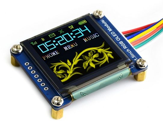
After having woken up my small 128×128 OLED display I was wondering how to get it to start automatically each time my rPi booted rather than having to log in and run the commands manually.

It turns out this is rather easy and just required me to edit two files. I’m also glad that these Waveshare OLED displays are effectively compatible with the Freetronics OLED 128×128 graphics display. A big thanks to the Freetronics team for making this driver available for SED1351 chip sets.

So I created the following file with my favourite editor (as root) /etc/modprobe.d/fbtft.conf with the following contents;

options fbtft_device name=freetronicsoled128

What this effectively does is tell the system how to configure the fbtft_device as it boots, much like if we started it with modprobe from the command line i.e used the following command;

sudo modprobe fbtft_device name=freetronicsoled128

So now the system knows how to configure the driver, we need to tell modprobe to load it by placing an entry in the /etc/modules file. So using your favourite editor (as root) edit /etc/modprobe and append the last two lines.

# /etc/modules: kernel modules to load at boot time.
#
# This file contains the names of kernel modules that should be loaded
# at boot time, one per line. Lines beginning with "#" are ignored.

i2c-dev
spi-bcm2835
fbtft_device

It appears that the SPI bus is a little slow to load if it’s called as a dependency of fbtft_device, which is a classic chicken and egg driver problem. So by starting it manually we make sure it’s available by the time the fbtft driver tries to do anything.

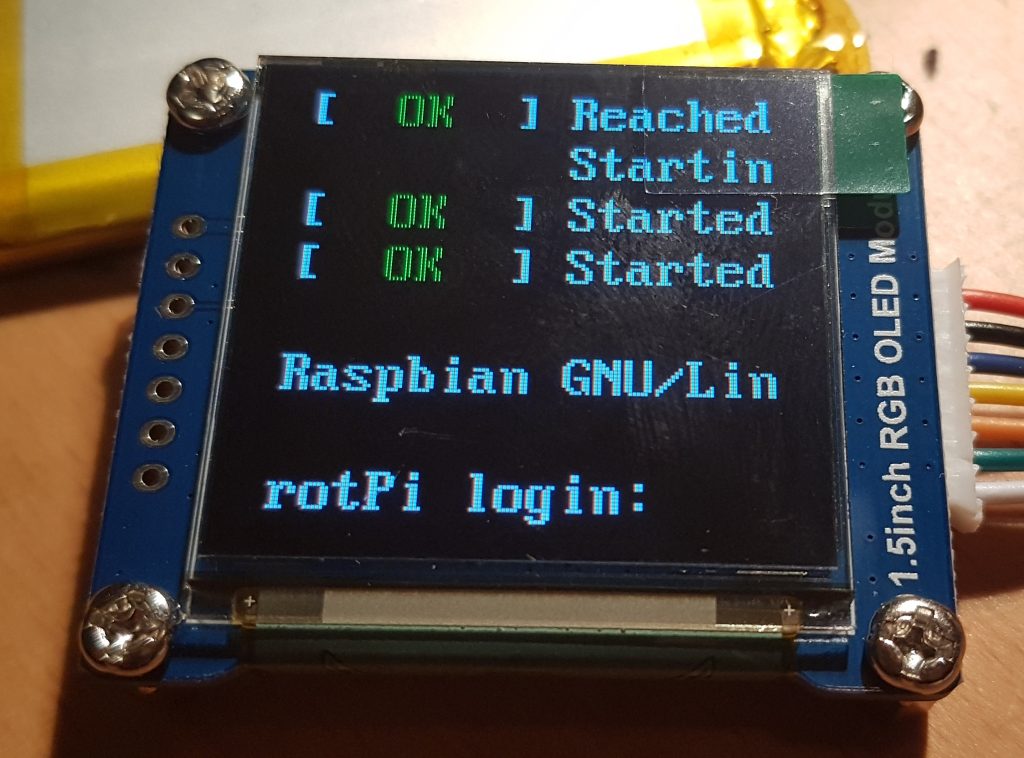
The i2c-dev entry in the same file fires up the i2c bus and was already pre-configured in my system by raspi-config way back when. I’m using it in my project, YMMV. All that is left to do is test it, so reboot and login and run the following command;

$dmesg | grep graphics

We should see something like the following;

[6.128978] graphics fb1: fb_ssd1351 frame buffer, 128x128, 32 KiB video memory, 4 KiB buffer memory, fps=20, spi0.0 at 20 MHz

That tells us that the little OLED display has registered as /dev/fb1 and that it’s ready to go. You can use the con2fbmap trick in my last post to test it’s working.

Now to work out how to get it to throw up an image on boot…

Small OLED Display on a rPi

Recently I was searching for a small graphic display that I could connect to a Raspberry Pi and fit within a Phoenix DIN enclosure I wanted to use.

There isn’t much space in the front of the enclosure I wanted to use, but a small 128×128 OLED colour display seemed it might fit.

Trawling through eBay I found what I thought to be a suitable unit and simply placed an order. There was very little information on the eBay site to tell me which display I had purchased so I just waited. When the display arrived it turned out to be a Waveshare SKU:14747 with the SED1351 controller.

A little searching around the web and I found an excellent tutorial written by the Freetronics Team for their 128×128 OLED display. It turns out our displays share the same SED1351 controller, so it was the logical place to start with my small display.

First task was to map the OLED pins to my rPi 3B+ 40-pin GPIO connector. On the rear of the display the pins and their desired function were clearly marked, so I mapped the pins like so;

OLED    | rPi      (pin)
--------+----------------
+5      | 5V       (1)
GND     | 0V       (3)
MOSI    | SPI_MOSI (19)
SCK     | SPI_SCK  (23)
CS      | SPI_CE0  (24)
DC      | GPIO25   (22)
RST     | GPIO24   (18)

I have also included the rPi pin numbers I used, make sure you plug the display into the right pins if in doubt RTFM. Once it was wired I ran the following commands to make sure the rPi was absolutely up to date;

sudo apt-get update
sudo apt-get dist-upgrade
sudo reboot

The latest version of Raspbian Lite I was using (Buster) came with the fbtft frame buffer drivers already installed, so these steps were unnecessary. Since this Raspbian installation was fairly recent I decided that I didn’t need to update the rPi firmware using the rpi-update command like in other tutorials; YMMV.

I had already enabled the SPI bus on my Pi when I was coming to grips with the I2C bus. I found the tutorial at Sparkfun a really good reference and easy to follow. To create the frame buffer for the OLED device I ran the following command;

sudo modprove fbtft_device name=freetronicsoled128
dmesg | tail -20

Fingers crossed we see the following output in our terminal;

fbtft: module is from the staging directory, the quality is unknown, you have been warned.
fbtft_device: module is from the staging directory, the quality is unknown, you have been warned.
spidev spi0.0: spidev spi0.0 125000kHz 8 bits mode=0x00
spidev spi0.1: spidev spi0.1 125000kHz 8 bits mode=0x00
bcm2708_fb soc:fb: soc:fb id=-1 pdata? no
spidev spi0.0: Deleting spi0.0
fbtft_device: GPIOS used by 'freetronicsoled128':
fbtft_device: 'reset' = GPIO24
fbtft_device: 'dc' = GPIO25
spidev spi0.1: spidev spi0.1 125000kHz 8 bits mode=0x00
spi spi0.0: fb_ssd1351 spi0.0 20000kHz 8 bits mode=0x00
fb_ssd1351: module is from the staging directory, the quality is unknown, you have been warned.
graphics fb1: fb_ssd1351 frame buffer, 128x128, 32 KiB video memory, 4 KiB buffer memory, fps=20, spi0.0 at 20 MHz

The output here shows us that the SPI bus is OK and that we now have a frame buffer /dev/fb1 that is expecting to find a SED1351 LCD controller. So now it was time to display something so I used following command;

con2fbmap 1 1

And here is what I see;

w00t it works ! Now it’s time to go and find some graphics libraries that can talk to this frame buffer device… and to work out how to display text in boxes that is wider than 80 columns in WordPress…