DMX RS485 Interface

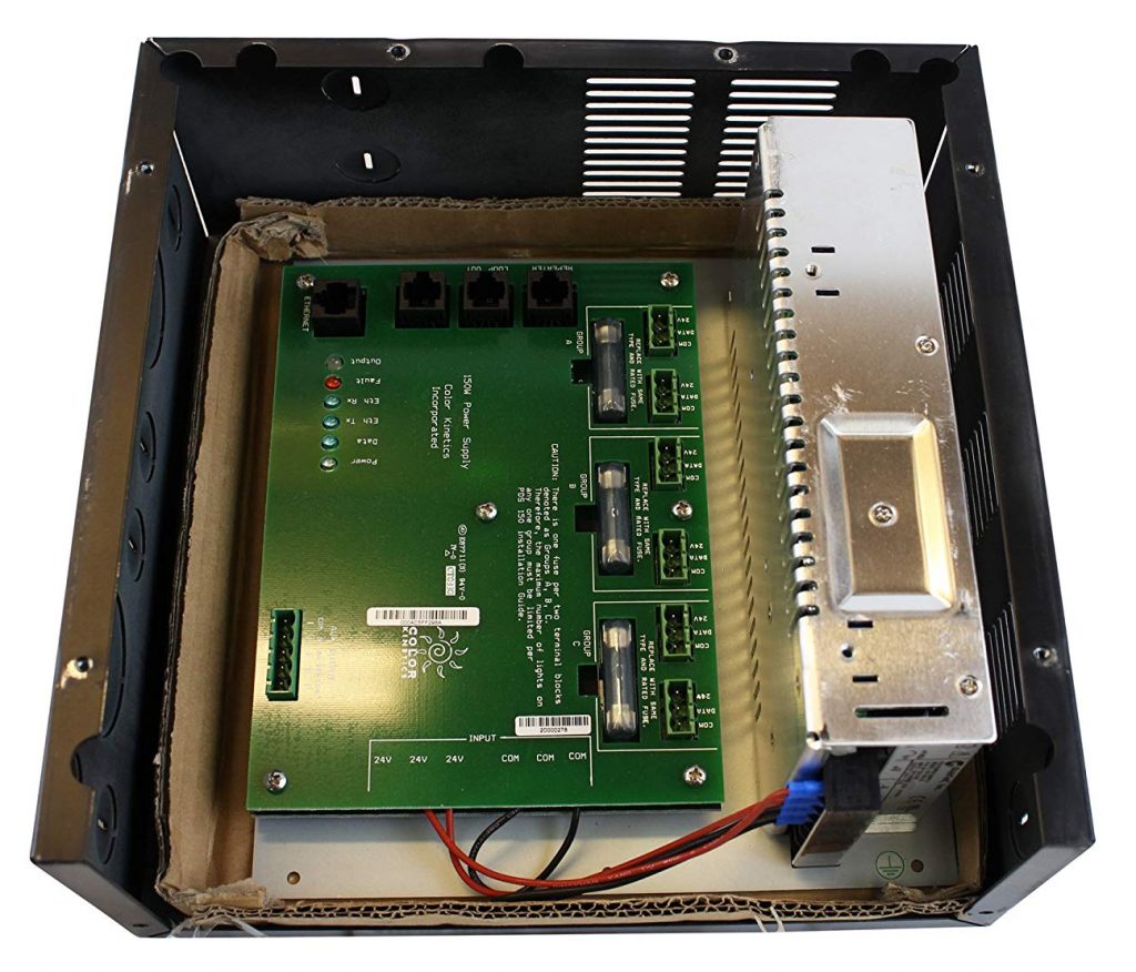
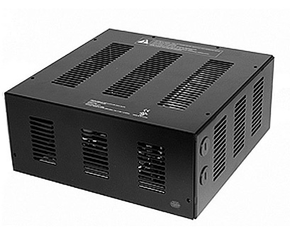
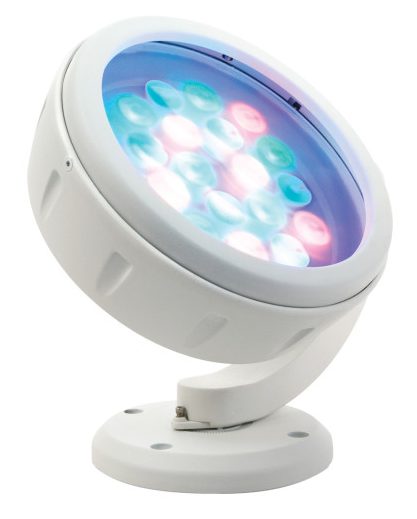
After having configured a Color Kinetics RGB LED driver I need a way to generate a DMX stream to validate it worked as expected. I searched my project boxes for some RS485 USB interfaces in my workshop, but as usual I had put them in a “special” place. So there was nothing for it but to crack out an Arduino and the soldering iron.

This isn’t the first RS485 interface I’ve built for an Arduino, but if you haven’t done it for DMX then I suggest reading this article on Instructables (click) that explains why the standard RS485 shields available are not suitable. However this interface (click) is one that I have found to work, just note that the TX and RX should be Pins 1 & 0 respectively and the enable input (ENB) should be connected to Pin 2.

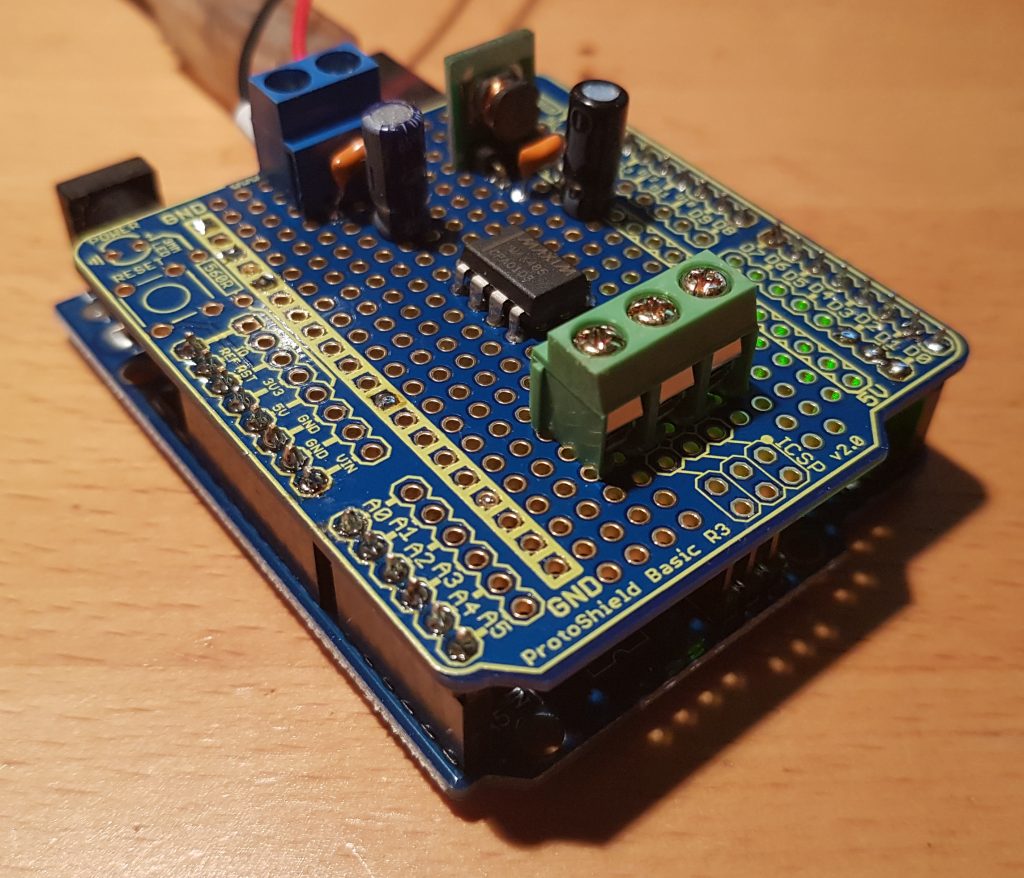
I like to use the Freetronics Basic Protoshields when building with Arduino’s they are different around the connectors and seem to have more clearance. The photo of the interface (right) was taken just prior to the RS485 safety resistors being mounted across the output of the RS485 bus.

I’d caution anyone against building RS485 interfaces without these safety resistors. With new RS485 receivers you can get away with out using them, but with older receivers they are mandatory. In a nutshell the safety resistors ensure there is always a 200mV differential across the receiver input that ensures the output of the receiver sits in the “UART idle” state. Otherwise what you find is the receiver will either not toggle it’s output or oscillate, in either case it doesn’t work. You just never know if the device you’re talking too has an old or new receiver, so it’s safer (boom boom) to have them than to not. YMMV.

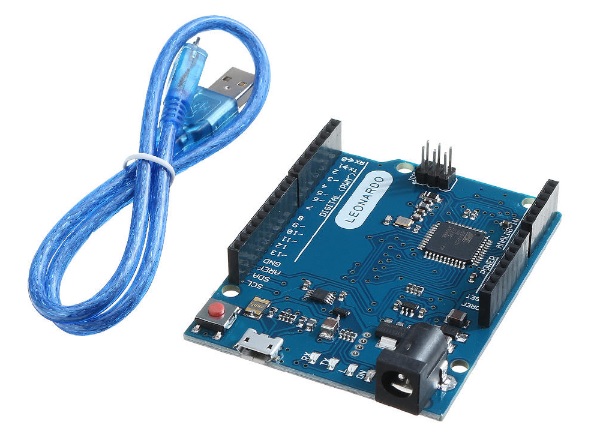
Once the basic interface was built I then realised that this wasn’t going to work with your standard Arduino Uno. You can’t share the UART with both the USB programming and serial debug interface with the RS485 driver without their being bus contention problems, steering resistors can be used with varying success. So the simple solution to this problem was to switch to a Arduino Leonardo, since they have both an on-chip USB interface for debugging and programming and a separate UART connected to pins 0 and 1. This was not without it’s own problems, so much so there is separate blog post to deal with these (click).

So all that was missing was a DMX library. Now this is something of a mine field, there are so many DMX libraries it got confusing finding the right one. After a lot of searching, downloading and fiddling I settled on the “DMX Library for Arduino” written by William van der Meeren (click). What set this library apart was it would transmit a full DMX 512 byte frame every 26ms from a much smaller buffer held in RAM that was non-blocking. It also has a mechanism to signal to the main loop when it had finished a full frame (click) allowing the firmware to quickly update the DMX channels and then allow it to carry on. This meant that colour washes could be kept atomic and smooth.

Below is one of the test programs that I wrote using the DMX library to test a few ideas on what may be possible with this interface. I have also included the PlatformIO config file that includes the necessary build flags;

#include <Arduino.h>
#include "Conceptinetics.h"
#include "math.h"

#define debug_output_enable()	Serial.begin(115200); while (!Serial){}
#define debug_output_f(...)    	Serial.print(F(__VA_ARGS__))
#define debug_msg_f(...) 	Serial.println(F(__VA_ARGS__))
#define debug_output(...)      	Serial.print(__VA_ARGS__)
#define debug_msg(...) 	      	Serial.println(__VA_ARGS__)

// structure to hold RGB colour information
typedef struct
{
  uint8_t red;
  uint8_t green;
  uint8_t blue;
} mycolour_t;

// DMX addressing information
const uint8_t DMX_DEVICES = 6;
const uint8_t DMX_CHANNELS_PER_DEVICE = 3;
const uint8_t DMX_CHANNELS_MIN = 1;
const uint8_t DMX_CHANNELS_MAX = (DMX_DEVICES*DMX_CHANNELS_PER_DEVICE);
const uint8_t DMX_BREAK_USEC = 200;
const uint8_t DMX_TXRX_PIN = 2;       // pin 2 used for RS485 TX/RX pin

// setup DMX master control object
DMX_Master dmx_master( DMX_CHANNELS_MAX , DMX_TXRX_PIN );

// convert sine wave to half wave, clamp value to zero for non-negative
// sine ouptut
float non_negative( float degrees )
{
  if( sin( degrees * DEG_TO_RAD ) < 0.0 )
    return 0.0;
  else
    return degrees;
};

// Initialise our hardware
void setup( void ) 
{
  /* Leonardo has separate USB serial port which is enabled when 
     plugged in.
  */
  debug_output_enable();

  // display something to user when deubgging
  debug_output_f("Mallee DMX Test\r\n Initialising...");

  // setup our DMX master
  dmx_master.enable();
  dmx_master.setChannelRange( DMX_CHANNELS_MIN, DMX_CHANNELS_MAX, 0 );
  dmx_master.setManualBreakMode();
  debug_msg_f(" Done!");

  // all done
  return;
}

// our main loop that will do stuff
void loop( void )
{
  /* Check if the DMX master is waiting for a break to happen, 
     the function below runs every 26ms (44Hz) which is the DMX
     maximum frame rate.
  */
  if( dmx_master.waitingBreak() )
  {      
    // Temp storage for RGB information
    mycolour_t colour;

    // local count variable
    static float angle = 0.0;

    // how much we'll increment our counter per frame
    angle += 0.25;

    //if we overflow wrap back to zero
    if( angle > 360.0 )
      angle = 0.0;

    /* calculate out our RGB values, including our phase offsets;
       not a lookup table in sight !
    */
    colour.red = (uint8_t)( 255 * sin( non_negative(angle + 120.0) * \ 
                            DEG_TO_RAD) );
    colour.green = (uint8_t)( 255 * sin( non_negative(angle + 0.0) * \
                              DEG_TO_RAD) );
    colour.blue = (uint8_t)( 255 * sin( non_negative(angle + 240.0) * \
                             DEG_TO_RAD) );
	
    /* Now we can update all of the attached devices, note that the DMX
       channels and the lamps are configured by the Color Kinetics 
       QuickPro software separately.
    */
    for( uint8_t i = 0; i < DMX_DEVICES; i++ )
    {
      //calculate DMX address for each lamp device
      uint8_t addr = (i * DMX_CHANNELS_PER_DEVICE) + DMX_CHANNELS_MIN;

      //update individual channels are sequentially addressed
      dmx_master.setChannelValue(addr+0, colour.red );
      dmx_master.setChannelValue(addr+1, colour.green );
      dmx_master.setChannelValue(addr+2, colour.blue );
    }    

    // Generate break and continue transmitting the next frame
    dmx_master.breakAndContinue ( DMX_BREAK_USEC );
  }
}
;PlatformIO Project Configuration File
;
;   Build options: build flags, source filter
;   Upload options: custom upload port, speed and extra flags
;   Library options: dependencies, extra library storages
;   Advanced options: extra scripting
;
; Please visit documentation for the other options and examples
; https://docs.platformio.org/page/projectconf.html
[env:leonardo]
platform = atmelavr
board = leonardo
framework = arduino
monitor_speed = 115200
build_flags =
  -D USE_DMX_SERIAL_1
  -D __DEBUG_ENABLED__

Color Kinetics PDS-150e

The Color Kinetics PDS-150e is an integrated power supply and driver that was popular during the early 2000’s. It is also the “magic” piece that I need for the Solar Mallee Trees project I’ve been working on.

Inside the unit is a power supply and integrated driver. Each of the six output channels are capable of driving up to 25W of RGB LED’s. So this is easily able to power a single Colorburst 4″ RGB LED per channel, they use just 10W. There are four RJ45 connectors across one size of the PCB that present Ethernet, DMX IN, DMX LOOP and DMX Repeater capabilities. I was certainly keen to see what we could do with the Ethernet interface. For these RGB LED drivers Color Kinetics offers a tool called QuickPlay Pro (TM) as a free download for Windows PC’s.

To use the Ethernet interface is relatively straight forward. The PDS-150e device is already programmed with an IP address somewhere within the classic 10.x.x.x Class A network. So I configured a Windows 7 laptop Ethernet interface with the arbitrary IP of 10.0.73.1 with a subnet mask of 255.0.0.0. I was simply crossing my fingers this wasn’t where the controller was, but it would allow the laptop and PDS-150e to find each other. I was pleased once QuickPlay Pro was started that I could find my PDS-150e listed in the “controller” drop down box. At a guess QuickPlay Pro and the PDS-150e either listen to a broadcast address or have some form of mDNS capabilities to “discover” each other.

Once I had connected QuickPlay Pro to the PDS-150e I was able to test the lamps individually, experiment with colour washing and configure the DMX channels and addressing. Below is an example of the colour wash function within QuickPlay Pro;

(C) 2019 Faith Coleman

I will have to say I’ve been doing this type of work for many years and Lighting Control Software has always been a painful experience. Either the software or devices would do “odd” things, not work, fart, spit, sulk or have quirks that required work around’s. However I was pleasantly surprised when QuickPlay Pro just worked, did what it said it would do without any fuss and or bother. So the Color Kinetics Engineering team have done a great job making this system work so well.

Once I’d gotten over my surprise it was a simple task to configure the RGB Lamps that I had into a sequential series of DMX addresses. Each of the Colorburst RGB lamps uses one DMX channel per colour (i.e. 3 channels for RGB), so I simply stringed the lamps together starting at address one;

DMX ADDR:  01  02  03  04  05  06  ........ 13  14  15
CB4 CH#:   R1  G1  B1  R2  G2  B2  ........ R5  G5  B5
Lamp       \---(1)---/ \---(2)---/ ........ \---(5)---/

One thing I did notice is that each Colorburst 4″ RGB lamp has a unique serial number that is displayed in QuickPlay Pro. This suggests that once each lamp is configured this won’t change if you start swapping the port it is connected too. I was pleased to find this is indeed the case, so once I know which tree each lamp is mounted too I can reconfigure the DMX addressing to be a little more logical.

Now I just need to start sending DMX at the controller and see if the lamps respond. Time to go and find a RS485 interface.

Mallee Solar Tree Project

I’m not sure sometimes how I end up getting involved with community projects and this one is no exception. This one started as a three way trade involving my ex-wife, her neighbour and a knee operation which of course all sounds very suspect. However the crux of the problem was a community group had acquired an art sculpture through the usual mate of a mate kind of thing. However as this sculpture was passed along bits were lost, forgotten, used for other things and/or misplaced. In a nutshell it wasn’t complete and no one knew if it even worked, or how. Well my ex-wife knew that I’d worked professionally on lighting control systems in a past life, so could I take a look at it. So here we go !

Image copyright Natasha Stewart
https://www.weekendnotes.com/profile/103314/

So what were we dealing with ? It turns out the art sculpture in question was the “Solar Mallee Trees” that were designed by MPH architects and were previously installed just outside the Festival Theatre in the Adelaide CBD. They were recently removed as part of a “refresh” of the entire site.

These “trees” were made from curved steel structures, had solar panels mounted to the top of them and a Color Kinetics lighting system. It uses LED RGB spot lights to wash the colour under the solar panels. However while the spotlights were present, there was no sign of any Solar Inverters, power supplies or controllers. This was suddenly not going to be easy.

Looking closely at what was present I found the LED spotlights were Color Kinetics Colorburst 4 (TM) and they appeared in good shape. These lamps require three wires so there is more to them than just applying power. Ok time to go and call a few people I know still work in the lighting industry.

Thankfully this was a fairly common lighting control system used in the Noughties and Color Kinetics (CK) still have much of the data, manuals and software available online.

My lighting industries contacts had advised me that I was up for a few thousand dollars to replace lamps, drivers and power supplies. So rebuilding what I had in hand was beginning to look promising.

To drive the Colorburst 4″ spot lights what we needed was a custom PSU that included driver and smarts, called a CK PDS-150e. What I really liked was this PSU/Driver had a separate DMX input and Ethernet programming ports; making it fairly easy to control once configured. Generating DMX information is fairly easy now days with software being available for windows and linux PC’s with the right RS485 serial interface. I’d certainly been there and done that many times in the past, so bringing up this system by rights shouldn’t be hard.

So finding a CK PDS-150e driver turned out to really easy, there were a number of them on eBay for just a few hundred dollars. It was worth the risk to see if I could get this working, if not I could always drop it back onto eBay and pass it on. So a CK PDS-150e was duly ordered and now it was time to read the manual a few times, download some software while the unit was shipped from Greece to Australia.

More to come.