ADALM Pluto Atomic Locked !

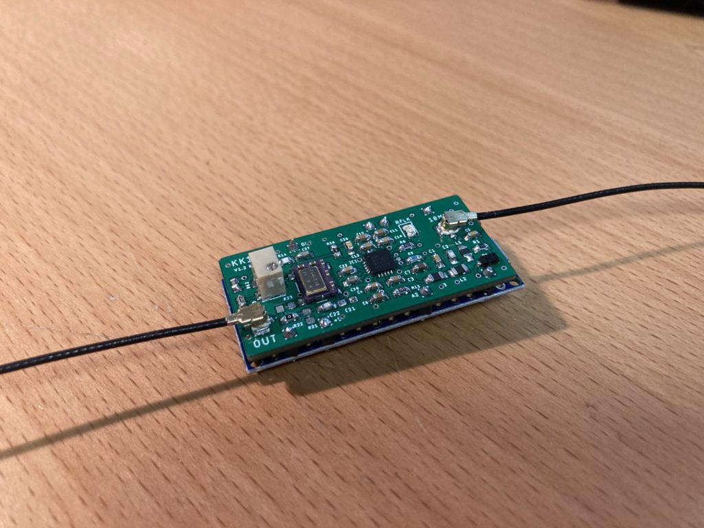
Now that the KK103c1 firmware is finished and capable of generating a 40MHz carrier that is phase locked to my 10MHz Rubidium reference, it’s now time to test everything is indeed working.

ADALM Pluto External Clock Input

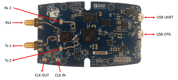
So up until now I’ve talked a lot about the ADLAM Pluto Clock input, but as yet have not shown where it is or what it does. From the Analog Devices Pluto University the following image below shows all of the inputs and outputs on the ADLAM Pluto. I’ll be feeding the KK103c1 into the “CLK IN” port, which is one of those lovely UFL connectors that are difficult to plug in without glasses or hellish with fat fingers, sigh.

So to make sure the “CLK IN” will work, we can look closely at the schematic for the Rev-C/D hardware and see what is there.

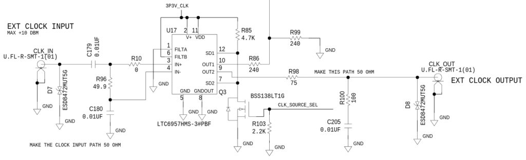
As per my previous post, the Connor Winfield VCO was not happy driving into a 50Ω load. It would also appear that the ADLAM Pluto has the same input impedance provided by resistor R96. Looking at the output of the KK103c1 driving into a 50 load, I see the output drop to +/-0.46Vp-p which is only just above the minimum input of the LTC6957 buffer being used to re-clock this input. So while this works, I will need to revisit this level and look at if I increase R96 to 200R to improve the signal levels provided by the KK103c1. Good enough for government work at this point in time. There is also a capacitor value that I can change to balance the KK103c1 output signal with the ADF4110 REFIN pin, to be investigated further.

Test Setup

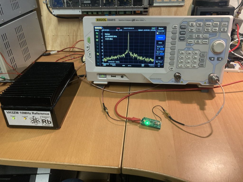
Once the External Clock Input was checked, the KK103c1 was connected by a short UFL-UFL lead to ADALM Pluto. I typically use a pair of tweezers and a microscope to get these things connected. The test setup is shown in the image below.

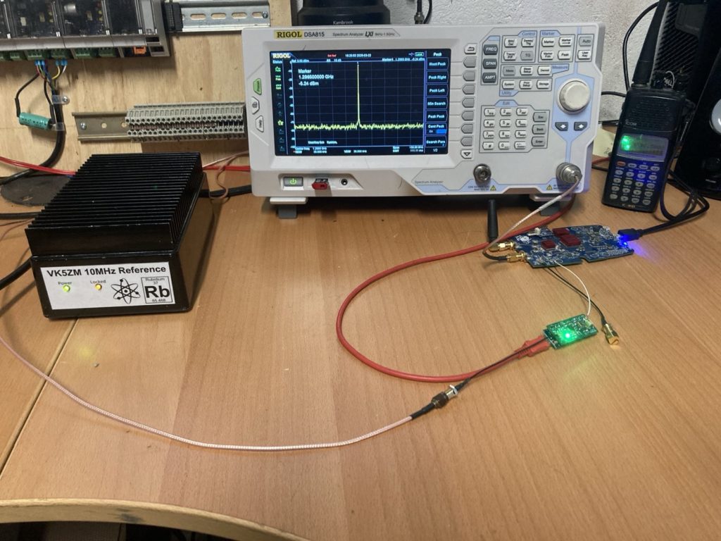
The 10MHz Rubidium reference was feeding both the Rigol external reference input and the KK103c1 module in the foreground. Again the Icom R10 was being used to listen to the carrier for any signs of instability, usually heard as clicks or warbling. I again used SDRangel to set the ADALM Pluto into transmit on 1296.5MHz wanting to keep this up towards the upper range of the Rigol scope so that any minor changes in the 40MHz clock would show up as error in the output frequency. I also deliberately de-tuned the VCO with the 10MHz reference not present to test that the PLL was in fact going into power down.

Internal vs External Clock Input

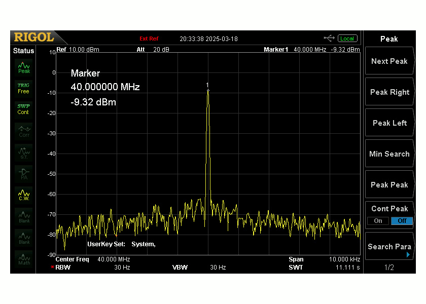
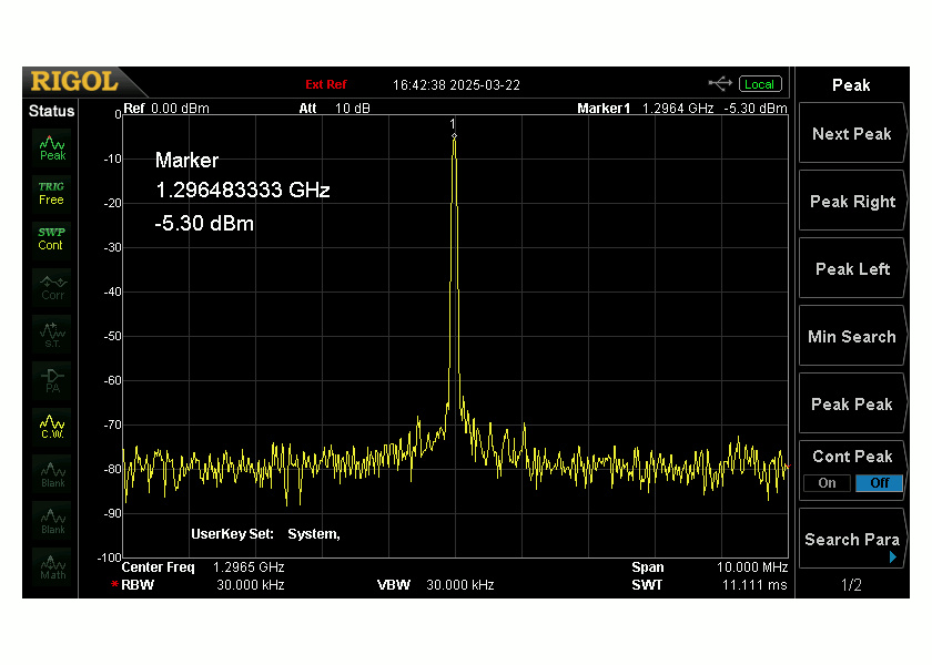
Below are the results from configuring the ADLAM Pluto to use it’s own internal oscillator vs the external 40MHz KK103c1 output. The following article from AMSAT DK goes through the process of switching the Pluto from it’s internal clock to external. The span has been reduced to 50kHz and the vertical scale changed to allow the spectrum analyser to find the peak. The results speak for themselves, that’s a lot of zeros.

ADLAM Pluto output, external 40MHz clock, 50kHz span
ADALM Pluto output, Internal Oscillator, 50kHz span

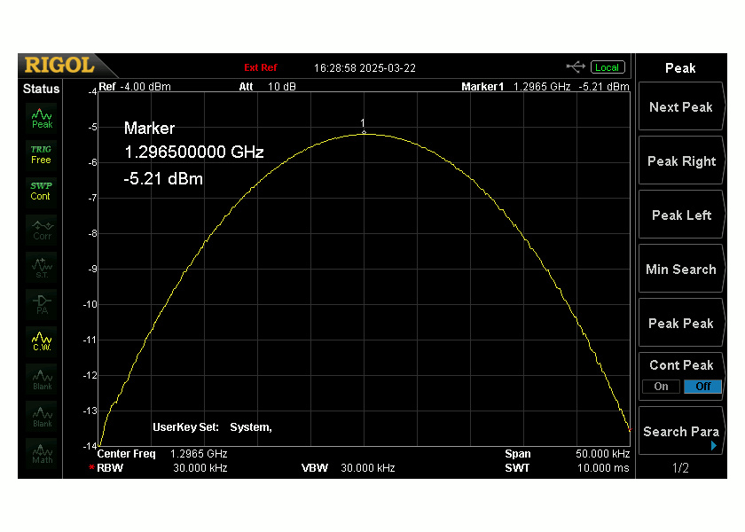
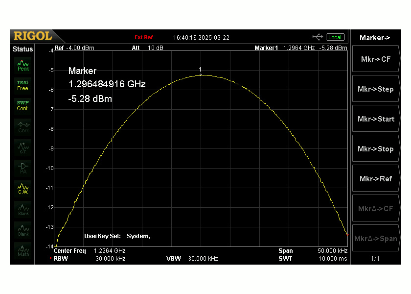
As can be seen in the image above. With the ADLAM Pluto configured to use the internal oscillator, there is 15kHz of error in the output signal, that simply disappears when clocked using the external 40MHz source. This was confirmed having to re-tune the Icom R10 to follow this change in output.

I’m certainly pleased with this result.

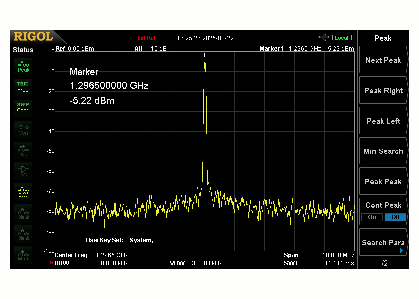
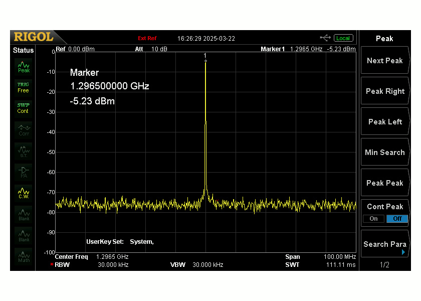
Carrier Spurs from external clock

It is typical to see Spurs appear if the reference oscillator does not have a clean or jitter free output. Widening the span to 10MHz and 100MHz respectfully, the output of the ADLAM Pluto remained spur free. Well at least within the limits of the Rigol DANL. There is some close in phase noise that needs to be checked with better equipment and perhaps when boxed.

ADLAM Pluto output, external 40MHz clock, 10MHz span
ADALM Pluto output, external 40MHz clock, 100MHz span.

Next Steps…

I still have to investigate the phase noise from the KK103c1 module when the opportunity presents. I will also be investigating the harmonic output of the Pluto Charon at the same time that phase measurements are made, the poor old Rigol is limited to an upper frequency limit of 1500MHz. Unfortunately the Rigol Spectrum Analyser is not quite metrology grade lab equipment, so this will all have to wait for a bit longer.

Now that I have the output of the ADLAM Pluto locked to my Rubidium source, it’s time to begin boxing this up into an enclosure with the Pluto Charon kit and finishing my 23cm all mode digital SDR radio.

Onwards and Upwards !

KK103c1 Firmware Development

Continuing with the development of an accurate 40MHz clock source for my ADALM Pluto, I recently finished an Arduino library to control the ADF4110 Synthesizer on a KK103c1 VCTXCO module. The KK103c1 module is a daughter board that sits on the back of an Arduino Nano.

I personally use the PlatformIO IDE extension within Visual Studio Code for all of my Arduino based projects. Yes, this even works on a Linux desktop machine. The PlatformIO ecosystem takes away the pain of getting embedded tool chains working, it’s simple and effective. I also don’t have to worry about tool chains that share libraries and break when incompatible versions are installed, and it deals with the library dependency hell problem that plagues the standard Arduino IDE.

Now that I was armed with a library that gave me basic control over the ADF4110 I could concentrate on writing a sketch that would make the KK103c1 do what I wanted it to do.

The code for this project has been published in my GitHub repository, you can find it here. The code has been released under a MIT license.

Firmware Description

The firmware is very simple and provides “just enough” functionality to allow the KK103c1 to externally clock the ADALM Pluto.

When the firmware starts it will load and configure the ADF4110 Synthesizer found on the KK103c1 module and set it to generate a fixed 40MHz unmodulated carrier, that is phase locked to its own 10MHz reference. It also checks that an external 10MHz reference is present using the diode detector on the KK103c1 and will flash the built-in Arduino Nano LED if not found. The MuxOut pin on the ADF4110 is also set to provide a Lock Detect output and a Green LED on the KK103c1 will burn your retina when the Connor Winfield VCO is locked on frequency.

If the external 10MHz reference is not detected or lost during normal operation, the sketch will also place the ADF4110 into power-down allowing the onboard VCO to “free-run”. The Connor Winfield VCO fitted to the KK103c1 is very accurate and stable on its own, so having the VCO free-run will see it hold +/-0.32ppm (+/-13Hz) over temperature, over a 1% voltage range including aging within a 24 hr period. The KK103c1 has a multi-turn pot that can rubber the VCO control voltage and trim the output to exactly 40MHz before the PLL has to do anything, this is a great feature for those that take their equipment out into the field.

The control range or “frequency pull-ability” of the Connor Winfield VCOs is specified as +/-12ppm which translates to +/-480Hz, so it is normal for the ADF4110 to reject the 10MHz reference if it is not within the same accuracy window. I commonly see the lock LED on the KK103c1 begin flashing as my Rubidium 10MHz reference is warming just prior to achieving it’s own atomic lock.

A PC can be connected to the USB serial and debug messages monitored that shows if the ADF4110 is locked or in free-run.

Pluto 40MHz Reference Oscillator - R0V1
---------------------------------------
* Checking Reference Oscillator level.......... Done !
* Starting kk103c1 ADF4110 PLL...
* ref freq = 10000000 Hz (detected)
* vco freq = 40000000 Hz (locked)
* Config complete.

Further debug messages can be enabled in the ADF4110-arduino library, look closely in the library header.

Testing Pluto 40MHz External Clock

So the proof is in the pudding. Below are images of the KK103c1 running my Pluto40MzExternalClock sketch along with plots from the spectrum analyser, as you can see I’m using my 10MHz Rubidium as the reference oscillator.

In the spectrum analyser plot above you can see the 40MHz oscillator “locked” to the 10MHz Rubidium reference holding the output frequency to better than +/-1Hz accuracy. The Spectrum analyser was also being fed from the same reference source, to ensure it wasn’t causing any additional error. This was also checked with my Agilent frequency counter again being fed by the Rubidium 10MHz oscillator.

One thing I have noticed is that the output of the KK103c1 was being loaded by the 50Ω input of my Rigol Spectrum Analyser. The Connor Winfield VCO has an internal series impedance of 200Ω so this behaviour is to be expected. I’ll have to look closely at the ADALM Pluto external clock input and see if I can change component values to suit.

With a working 40MHz clock, phase locked to my 10MHz reference, it’s now time to hook this all together and see if I can improve upon the ADALM Pluto frequency accuracy.

More to come.

ADF4110 Arduino Library

In a recent post I was fortunate to obtain a 40MHz VCTXCO module from David VK5KK that I am using to lock an ADALM Pluto to an external 10MHz reference.

David’s design uses the Analog Devices ADF4110 RF Frequency Synthesizer, which offers low phase noise and operation up to 540MHz, more than enough for this application. It was also conveniently packaged as a daughter board for an Arduino Nano.

However upon entering the keywords “Arduino ADF4110 library” into Google & Duck-Duck-Go I was not greeted with any results. Oh dear, I have to write a library myself how strange ! Time to dust off my Arduino development environment.

I am not intending to describe how a Frequency Synthesizer or Phase Locked Loop (PLL) works, there are many YouTube videos and articles on the internet that can describe this better than I. If you are interested in the KK103c1 40MHz VCTCXO module I’m using, you can find it published in Dubus Q3/2022, there David also goes into some detail of how it works.

For this Arduino library the ADF4110 contains three internal 24-bit latches, where we can program the necessary values into counters and configure the hardware to generate the desired frequency output. This is achieved with a series of bit-shifting and bit-manipulations macros within the code, I have followed the names and bit-naming structures as per the Analog Devices ADF4110 datasheet.

The ADF4110-Arduino library essentially consists of five functions, that are described in the README.md. There is the ubiquitous Arduino “begin” function used to configure the SPI communication between the ADF4110 latches and Arduino Nano, there is an “initialise” function to load & initially configure the hardware of the synthesizer, an “update” function to simply change frequency and two utility functions to “print” the frequency to the serial console and another to “powerdown” the synthesizer when necessary. This was all I needed to get my synthesizer going, it should all hopefully be self-explanatory.

Now that I have the ADF4110-Arduino library essentially working, I can now focus on using this to drive the KK103c1 module but that is for another post.

ADALM Pluto Frequency Accuracy

In a recent post I had my ADLAM Pluto transmitting using SDRangel on 1296.5MHz listening to it using an Icom R10 receiver. One thing that I did immediately notice was I had to tune the R10 down 15-18kHz to get both systems “on” frequency. One or both of them had to be off frequency, so which one was it ? After a few measurements with a spectrum analyser, I found the ADALM Pluto was the culprit, surprisingly the Icom R10 was within a 100Hz of where it was supposed to be.

So… the ADALM Pluto was at least 16.667kHz low using its internal 40MHz crystal reference, that is not going to cut the mustard on these higher bands.

I had always planned on phase locking the Pluto to an external 10MHz Rubidium reference. The only catch is the external reference input on the Pluto expects a 40MHz clock and the AD9361 transceiver within the Pluto, cannot be configured to use a reference clock much below 25MHz. So there was no way I was going to make this work with a 10MHz reference without adding something in between.

After some further research I decided I needed a 40MHz VCO that I could phase lock to the external 10MHz reference to solve my problem with the Pluto external clock input. A chance discussion at a conference in Tasmania at the end of 2024 lead me to laying my hands on a KK103c1 40MHz VCTXCO PCBA designed and built by David VK5KK.

David’s 40MHz VCTCXO design was published in Dubus Q3/2022. It was designed as a daughter board directly connected to an Arduino Nano, that it conveniently sits on top of. The specs for this board were perfect for what I was planning to do with the Pluto external clock input;

Ref In:     10MHz, -4dBm to +14dBm
Output: 40MHz ~1.0Vp-p (into 200R)
VCO: Connor Winfield T604
PLL: Analog Devices ADF4110
Micro: Arduino Nano ATMEGA328p

Both the VCO and PLL are low phase noise varieties and the power supply decoupling is extensive. I was even given a basic Arduino sketch that I could use to test the board, that is provided I had an Arduino Nano. Oh well Nano ordered and should be here soon.

Certainly once I have this board running, I’ll be doing some phase noise measurements and experiments with my Rubidium 10MHz reference. It will be interesting to see what improvement I get in frequency accuracy, along with comparing the phase noise of the internal Pluto clock and seeing if there are any differences. However before this I’ll need to write some Arduino code to tailor this board for my purposes and perhaps a library to drive the ADF4110. That will of course land somewhere in my GitHub repository when ready.

I’ll give a shout out and my personal thanks to David VK5KK for gifting me one these boards and accelerating my ADLAM Pluto project. I certainly can’t wait to get to testing once the postman delivers a Arduino Nano. I know I’ve got some Nano’s somewhere, but for the life me of I can’t find that box.

More to come.