
Soldering anything with a large thermal mass is tricky business. Often when faced with this situation I crank up the temperature on my Hakko soldering station well into the +450°C region, wet the tip with solder and try to pour enough heat into the joint to get the solder to bond well. The downside is often the heat is drawn away from the joint, which means you’re heating the joint for far too long and materials start to burn. PCB laminate is typically OK to temperatures of 140-170°C for short periods before they turn brown. Likewise any flux does not get a chance to remove oxidisation and results in contaminated joints.
The best solution is to use a hot plate, which will bring what you’re trying to solder to a per-heated stage before you apply the iron. This is effectively a “manual” version of reflow soldering, I’ve tried to draw a typical reflow profile below.
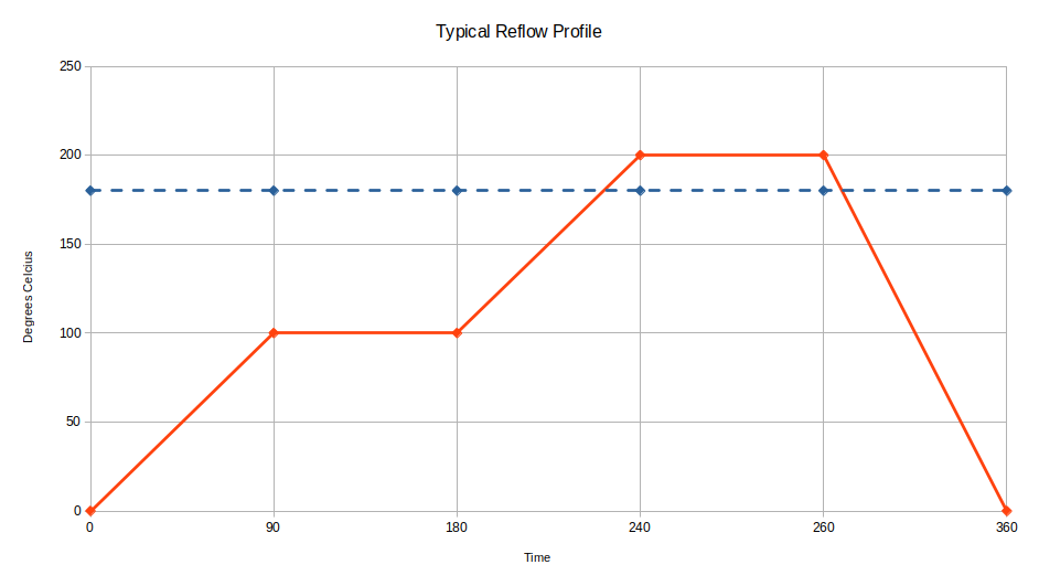
There is a lot of information about the above curve on the internet, needless to say I intend to use the hot plate to give me the preheat and dwell time to activate any flux (first flat part), and then use my soldering iron to melt the solder (peak) and then allow things to cool down.
So the next question is where do you buy one ?
Searching in various places I noticed that online there was a plethora of some cheap Chinese hot plates for what seemed like very little money. I couldn’t build one for the price being offered. Wondering what was inside I found the following tear-down video, which suggests while they work there are some potential issues with their electrical safety.
Curious I ordered one and waited for the postman to deliver. Like the author above I found that the internal wiring of this unit was non-compliant to Australian safety standards, which shouldn’t come as a surprise as the unit had no safety markings at all; making these units technically illegal to import and use.
However I’m fortunate to work within the Electrical Industry, so I have access to the relevant safety standards and could modify my unit to make it compliant and therefore safe. Before anyone asks, no I cannot provide details of what I did to my unit. There are more things to consider than just the earthing, as was done in the above video. It took me quite a number of hours to fix the issues I found with this unit. I would suggest that others look for and buy hot plates that have the necessary RCM/UL/CE markings relevant to your country.
With the safety issues resolved I could set to testing the operation of my unit to see if it indeed worked. I placed a K-Type thermocouple into my trusty multimeter and set too testing various temperature settings with various materials.
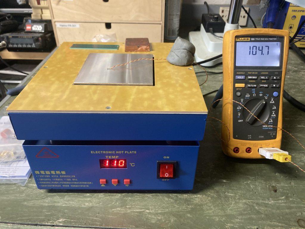
With the thermocouple sitting on the middle of the plate, the 7-segment set temperature and temp reading on the multimeter were close enough for government work. In case you were wondering +100°C is hot, so best not to touch the plate or attempt to pick up the items left on the plate for any period of time, ouch it will burn.
I do like the fact the hotplate on this unit is small, with a fiberglass surround. The fiberglass surround allows me to place my hands either side of the hotplate, without fear of being burnt. It also means I can use mechanical weights to hold things down as I solder them to various places. Hence why I could use a ball of blue-tac to hold the thermocouple wire.
On the 7-segment display the right most decimal point will flash as the heater element is switched on and off. Watching the hotplate warm-up and the 7-segment display decimal point, it would appear that some form of pulse integral control loop is being used with its own internal temp sensor. The plate warms reasonably quickly but will slow down as it approaches the set point, there was no signs of overshoot which I was happy with.
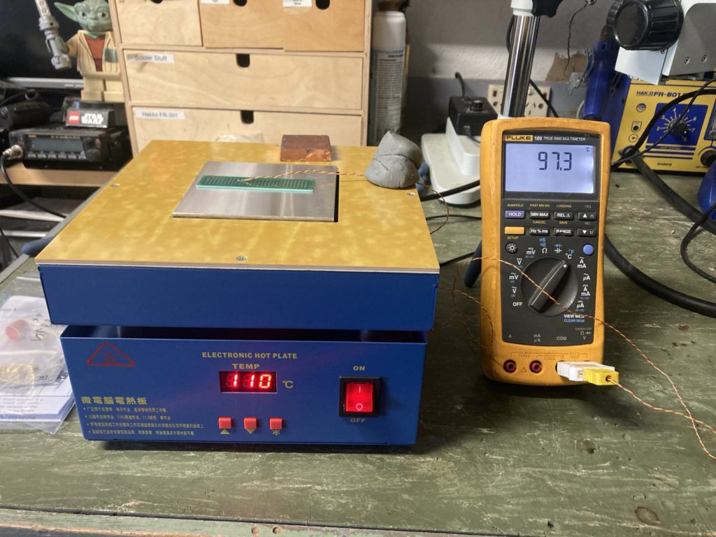
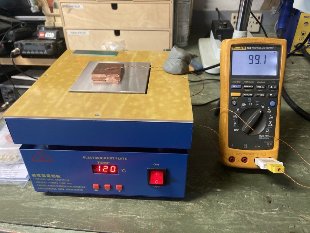
Once the main hot plate temperature was stable, I placed an old piece of PCB laminate under the temp sensor and watched the temperature on the thermocouple slowly increase. Needless to say after a couple of minutes the temperatures once again were close enough. I did adjust the set point up to +110°C as there is some noticeable thermal resistance across FR4 laminate. Likewise the copper block took a little longer at 5-6 minutes to warm up to temp, again I had to increase the set point to +120°C as copper is very good at dissipating heat, so this was of little surprise. All in all the thermal performance of this unit was good.
This hot plate should have at face value represented a real bargain, had it not been for the internal wiring and safety issues. I cannot stress how important electrical safety is, mains voltages are lethal; so please consider purchasing another unit that has the relevant safety marks.

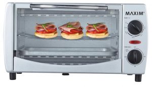 I’ve been doing a lot of PCB assembly of late both re-flowing SMD in a toaster oven and a heap of hand soldering. One thing that bugs me is cleaning up the various rosin’s, flux and solder paste without making a bigger mess.
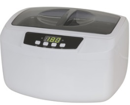 Thankfully my local
  The PCB wash was yet another story. This stuff is far cheaper in large quantities but I just wanted a little bit to see how we go. So I found Jaycar also sold 1L bottles from Chemtools which you can find here (