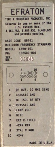
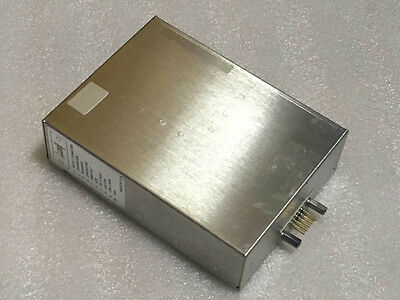
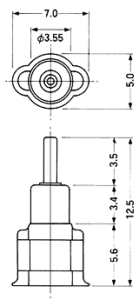
The Efratom LPRO-101 reference guide has the necessary drill pattern for mounting the reference oscillator within an enclosure. The one thing to watch, that caught me out, is the two screws in the middle are not on the centre line of the unit, it’s offset. It doesn’t look like it until it’s too late. So make sure you measure twice and drill once or you will write off a die-cast box or two.
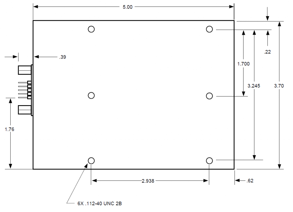
This module is somewhat difficult to mount to a heat sink since the spacing of the mounting holes do not line up neatly with any heat sink profiles I could find. So instead I’ve mounted my module to the bottom of my die-cast enclosure with countersunk screws and will then mount the die-cast box to the heat sink. So the die-cast box is effectively sandwiched between the rubidium reference enclosure and heat sink.
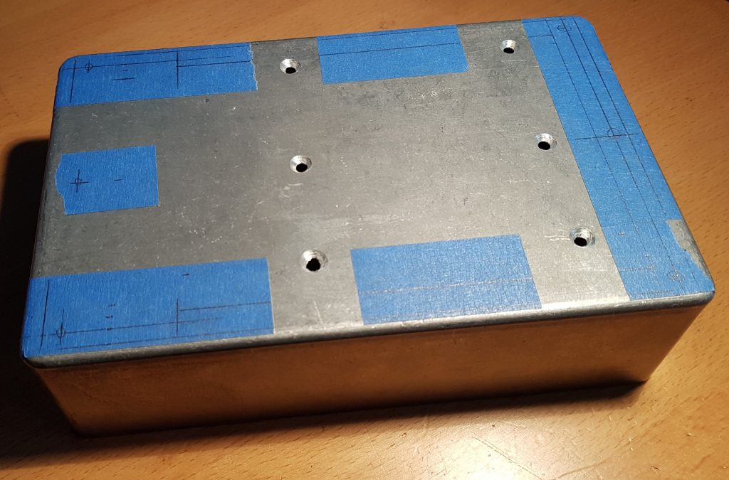
As a graduate engineer I was once shown by a senior tech a great way of marking up and drilling die-cast boxes without marking the face. Basically you cover the areas where you want to drill holes with masking tape and use a pencil or drafting pen to mark the tape. You can then centre punch your holes, remove the tape and drill. Below is the bottom of my Hammond 1590D enclosure marked out with the holes for the Rubidium reference.
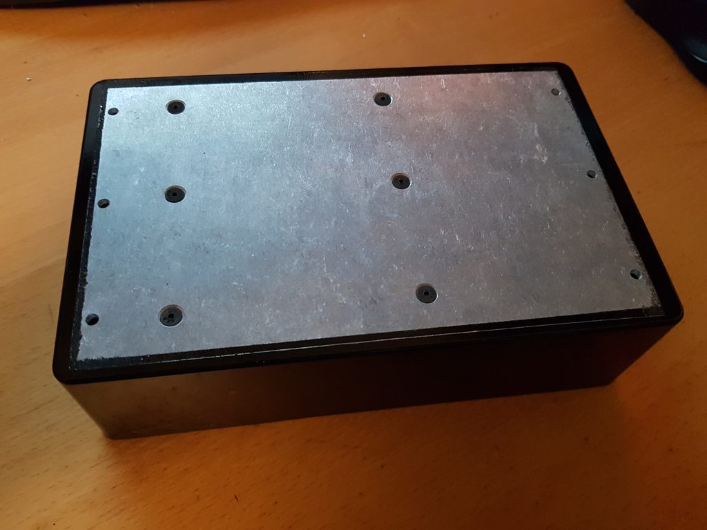
Here I’ve drilled the mounting holes for the Rubidium for a test just prior to making the decision to drill the heat sink holes. After drilling and tapping all necessary holes the box and lid received two coats of etch primer and then two coats of gloss black. There are times I just hate gloss black, it shows all the imperfections and it is so easy to mark. I’ve learnt that if you want a good finish, make sure you spray and bake the final coat in a small toaster oven set to 70-80°C for an hour. So after painting it looked like this;
Paint has a terrible thermal conductivity, so I’ve taken the time to mask off the top of the box so I can put thermal paste (white goo aka jump grease) between the heat sink and box at final assembly. Above you can see the black heads of the 1/2″ 4-40 UNC 2B screws required to pull the rubidium up against the lid. In the thermal management section I’ll talk a little more about how I’m going to get the heat out of this module. This is what it looks like when turned over;
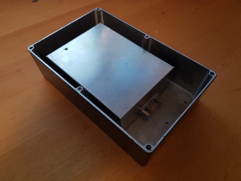
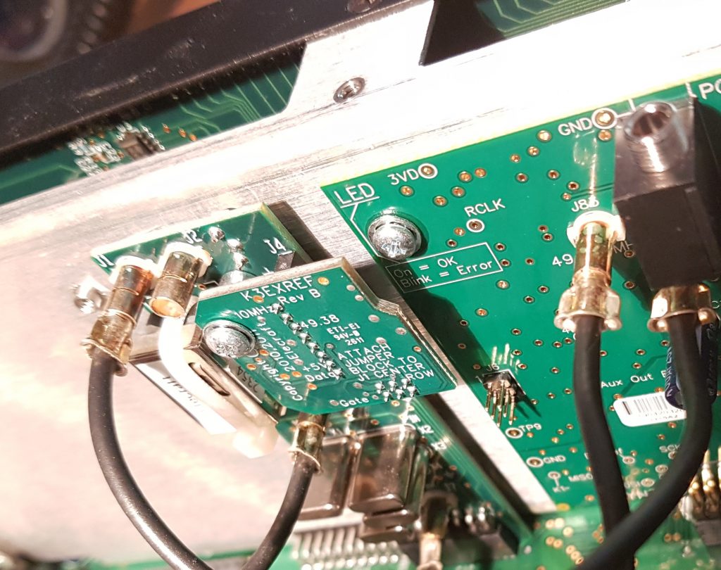
If you look closely you’ll see it’s centred within the enclosure, which means I was paying attention to the two holes in the middle of the enclosure being offset (*grin*). There are also holes in either end of the enclosure for LED’s, SMA connector and power to be connected when final wiring takes place.
Once the body of the box had been done I could turn my attention to the heat sink that mounts on top. Again I used my tape mask trick to mark and drill the holes that went between the fins. Each of these holes was tapped with a M3 thread so that screws could be mounted without the aid of nuts and washers.
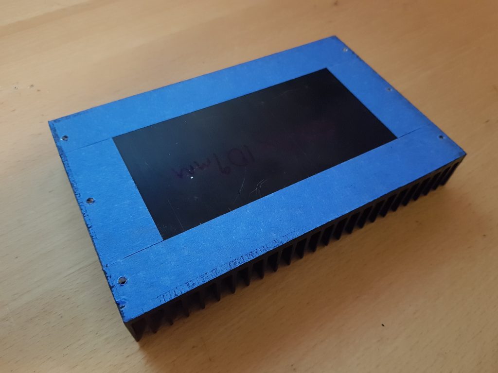
The heat sink unfortunately was a little large and had to be cut down. I am luck to have a workshop at work with an engineering band-saw fitted with a bi-metal blade. So it wasn’t difficult to cut the heat sink down to the right size and then repaint. One of these days I must learn how to do black anodising with dye. So dry assembled we get this effect;
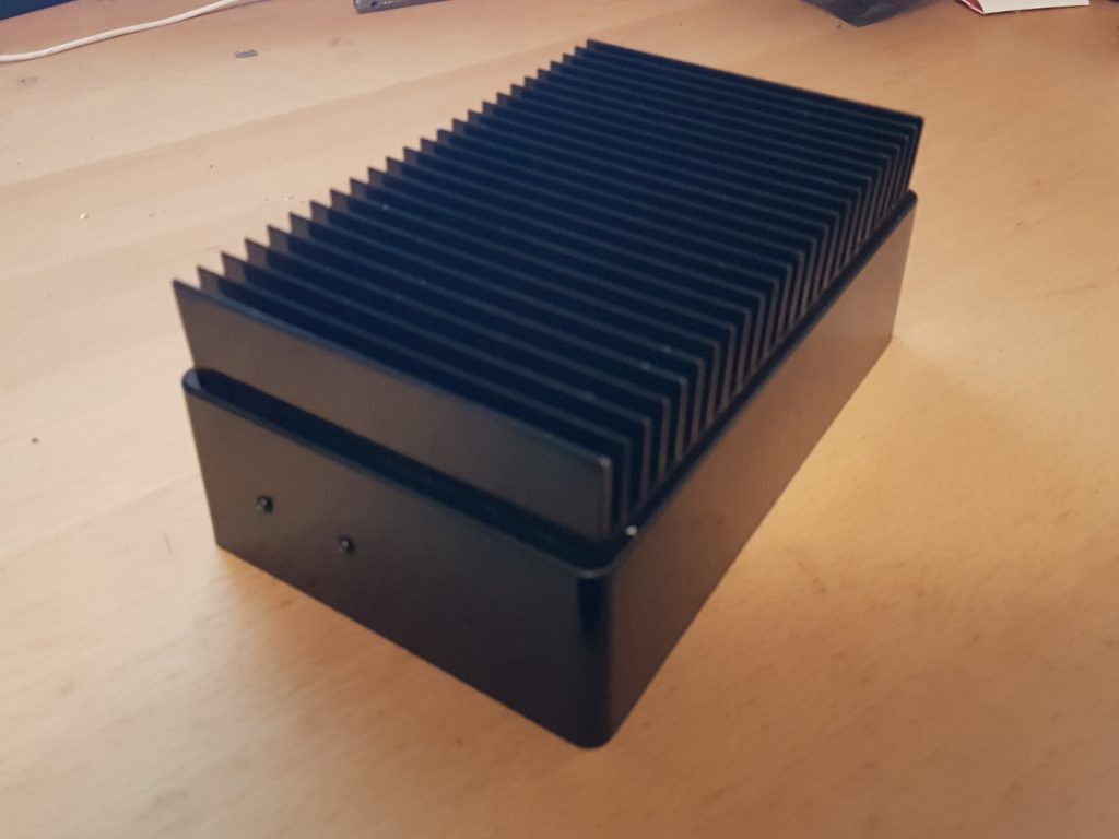
Which looks rather snazzy. Now to finish off the thermal design.

 I’ve been doing a lot of PCB assembly of late both re-flowing SMD in a toaster oven and a heap of hand soldering. One thing that bugs me is cleaning up the various rosin’s, flux and solder paste without making a bigger mess.
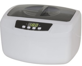 Thankfully my local
  The PCB wash was yet another story. This stuff is far cheaper in large quantities but I just wanted a little bit to see how we go. So I found Jaycar also sold 1L bottles from Chemtools which you can find here (