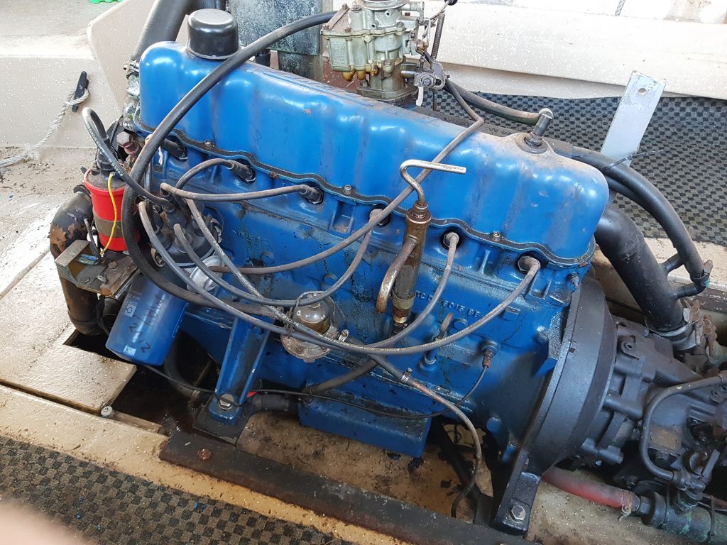
While changing the oil in my Nereus I was watching the temperature gauge and noticed that the engine temperature would warm up to 95 degrees before the thermostat would open, once open the temperature would drop markedly to 80 degrees before finally settling at 85 degrees. It was quite clear that the thermostat was faulty if not on the way out. There was no way I could leave it like that.
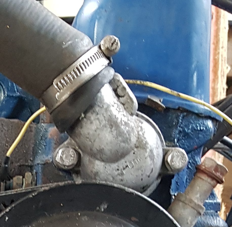
Since this boat has a heat exhanger the thermostat is the same as used in a car so replacement parts shouldn’t be hard to get from the auto parts store. The thermostat is hidden behind the usual cover at the front of the engine;
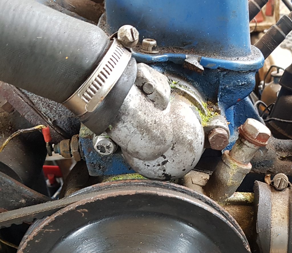
It also looked like the gasket was not sealing well with evidence of a small leak having occurred at some point. The downside of replacing the thermostat it would require the coolant to be drained, so it’s was also time to also service the heat exchanger and kill two birds with the one stone. Note to self I need to find out what’s required here.
The first surprise upon pulling the bolts out of the old thermostat cover was the bolt on the port side was mild steel and was only being held by three turns, it was a little short. The other starboard side bolt was stainless and much longer (32mm cf 25mm). A quick confirmation with a set of vernier calipers told me the right length was 32mm. Now this engine is from the period where metric and imperial co-existed in Australia. So it was highly likely the bolt as 5/16 imperial and not 8mm metric. So a quick measurement with a thread gauge confirmed it was a 5/16 UNC 1 1/2″ long bolt that also required a split washer, so off to the bolt shop we go I don’t have much in the way of imperial bolts in my workshop.
The thermostat housing was a little pitted, so that was duly rubbed on the concrete with a circular motion to grind away some of the surface material to remove the pits (easier than sandpaper and a sheet of glass if you don’t have it) and all traces of the gasket were removed with a utility knife. The thermostat also came with a new paper gasket, which was duly coated in Hilomar M to ensure a good seal and then re-assembled.
It doesn’t look much different than before, except the keen observer will see the bolts have changed just a little and there’s no sign of that coolant leak. The proof will be that it doesn’t leak.
The last task was to get all of the coolant out of the bilge, so to the pumps… well the bilge pump at least. Before I threw the coolant all over the driveway the outlet was redirected into a bucket and fresh water used to dilute the coolant sufficiently until no more “Green” was observed in the bilge discharge.
Time to move onto the Heat Exchanger before re-filling with coolant.