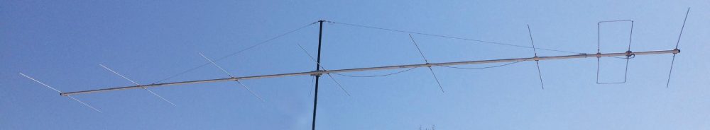
Recently I came across a novel way to get the ADALM Pluto to generate a 10GHz signal. Jay Francis presented a minimal ADALM Pluto 10GHz transceiver system that used a commercial LNB and some Mini-Circuits high pass filters, to pick off the 3rd harmonic from the TX output. You can watch his video below.
This got me thinking, could you actually build a 10GHz transceiver from the ADALM Pluto like the 23cm Pluto Charon kit I’ve been working on ?
Now I don’t have any of the Mini-Circuits high pass filters and they were a little expensive to get shipped to Australia, but I did know of a 10GHz Frequency Multiplier kit from Minikits being manufactured locally. The Minikits kit comes with a GAL-39, 10GHz pipe cap filter and a NLB310 post amplifier that can be assembled on a universal microwave board. Whilst designed to double a 4-5GHz signal up on to 10GHz, it can also triple a 3-4GHz signal with a bit of tweaking and fine tuning. This was perfect for what I was planning with the ADALM Pluto, so one was ordered and I had to wait for the postman for it to arrive.
While the Minikits multiplier was on its way I also stumbled across N1BUG’sYouTube channel, where he walks you through how he assembles 10GHz pipe cap filters in his workshop. It was quite clear that some “real” heat is required, so I also purchased a Chinese made hotplate to assist with additional heat when soldering the cap itself. You can find more about that adventure here.. So far I’d spent less than the cost of two Mini-Circuits high pass filters.
I’m now sure that 10GHz pipe cap filters look bigger on the computer screen than they do in real life. I was genuinely surprised just how tiny they were. I was also questioning the purchase of a hotplate.
Following the Minikits multiplier kit instructions, I first drilled and tapped a M4 hole in the pipe cap, prepared the probes, modified the board to accept the pipe-cap and then proceeded to solder it down. Since I was using a hotplate, I decided to solder the pipe-cap down first, then solder the probes in after as suggested by N1BUG. This meant I needed to pay attention to the probe straightness and length, so that they would land in the right place once assembled. I was OK with this as I can see the probes through the M4 nut in the top using my microscope before and after soldering.
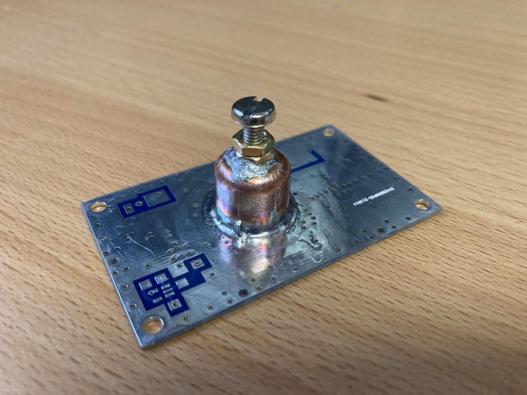
Now soldering this pipe-cap was genuinely difficult and the hotplate certainly made the job much easier. The flux that I used was not that great, I must try to find some of the really gooey sticky flux that N1BUG was using. However I persevered with my Hakko 50W iron wound up to +450°C with a K-tip and some 0.7mm solder rings, tacking and working my way around the cap. Once I’d placed sufficient solder, I then broke out the hot-air gun set to +400°C and re-flowed the joint, which gave me a much neater and more uniform appearance.
Below is the board after soldering and once I’d cleaned up the excess flux. The Minikits PCB has quite a few holes in the plane, so I used compressed PCBA flux cleaner blown in through the nut to make sure no residual flux was present after soldering. Likewise a small file and knife were used to clean up the blobs of solder around the nut.
For my first attempt at soldering pipe-cap filters I’m happy with the result. I found the hardest part soldering the nut to the top, mainly due to difficulties applying flux and getting the solder to wick to the nut and cap evenly.
So the next steps are to insert the probes and build the associated amplifiers and then test and tune. More to come.
So it’s been a while since I’d looked at my ADLAM Pluto SDR project, to complicate matters I’ve also recently switched to Linux. So it was time to see if I could find new SDR software to drive it.
After a few false starts and some trials and tribulations, I finally settled on SDRangel. I’ve used this app before to demodulate a High Altitude Balloon payload that transmitted a quirky DVB-T modulator using a RTL-SDR and Ubuntu Laptop.
So the only problem, SDRangel is written to natively run on Ubuntu, Windows, Mac and the rest of the distros can either use a snap package or compile from source. Sigh. Linux Mint does not like snaps, LMDE uses only flatpak’s.
SDRangel Flatpak
Now I’m not a big fan of flatpak’s either, to me they are in the same boat as snaps and docker images, unnecessarily slow, however after reading how to compile SDRangel from source, a flatpak was certainly the fastest and easiest way to let me try the software and see if I can get this working.
Thankfully I found SDRangel on Flathub. The following was all I had to do from a command line to install the flatpak, installation instructions were found here.
After a short time downloading and installing it was ready.
SDR plugable UDEV Rules
SDRAngel requires udev rules to be added for the most common SDR’s, since I also intend to try RTL-SDR’s at some point, now as as good as any time to install.
The udev rules can be found here on the SDRangel GitHub repo. I simply downloaded them in a zip file to my local downloads directory, unzipped and moved them into /etc/udev/rules.d. There is an installation script (install.sh) in that same directory as the downloaded udev rules you can use or read for inspiration on the linux commands necessary.
If you find that you still can’t access these devices, check your user has the right permissions to use USB or network devices, trap for young players and outside the scope of this post. Google and Duck-Duck-Go has lots to say on this topic.
Flatpak Permissions
Before starting SDRangel I also loaded Flatseal and checked what permissions the SDRangel flatpak was requesting. Always pays to review flatpaks using Flatseal, I’ve found a few packages that had some very odd permissions and didn’t work on LMDE out of the box.
It makes sense to me to grant SDRangel access to the network, PulseAudio sound server, GPU acceleration (if used), All devices (i.e. SDR’s) and the “Run in Background” option. This is the config that worked for me, YMMV.
SDRangel Configuration
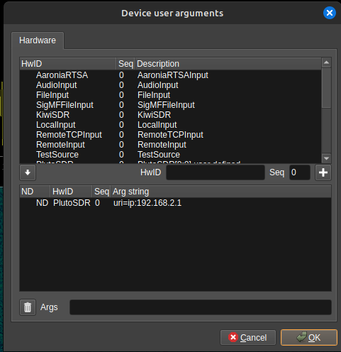
Once SDRangel is loaded, we’re greeted with a big blank screen. From here I added the ADLAM Pluto by clicking Preferences > Devices > User Arguments
I then added “PlutoSDR” in the HwID field, left seq as 0 and hit the ‘+” button which is the add symbol. I then selected the PlutoSDR entry in the lower pane, added “uri=ip:192.168.2.1” in the Args field, and hit OK. After I’d finished my config screen looked like this. Note my IP is the default PlutoDVB value, you can find what yours is set to in the config.txt file from the Pluto storage device it presents when connected to a PC. Now apparently you need to restart SDRangel for this to have any effect. YMMV.
Adding a RX Device
I then added an RX device by clicking on the menu button just to the right of the purple button with a play symbol in it. If you hover over each button, a pop up appears telling you what the button is. From the drop down box, I then selected the PlutoSDR entry which was right towards the bottom of the list.
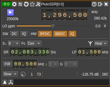
Two screens appear, but we’ll concentrate on them one at a time. I configured the Receive window like this, more info here;
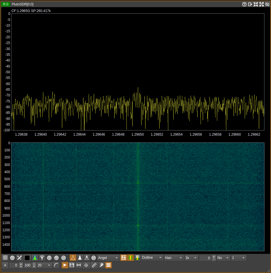
Now the thing to note. I’ve twiddled the sampling rate for reasons I’ll explain in another post. You should find the initial settings of 2.5MHz work well enough out of the box. I’ve increased the decimation from 1 to 8 in the S field, likewise I’ve selected “slow” AGC. If you then press the purple button with the white play symbol, you would see the next window start to do something interesting like this.
I didn’t change anything here, the out of the box config just worked for me. Now you might notice you don’t hear anything, that is because you have to add a channel/separate demodulator. On the receive window, just to the left of where “PlutoSDR[0:0]” appears is a button you can click to add a channel.
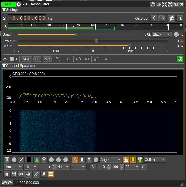
From the pull down box I’d choose the SSB Demodulator, which will appear on your screen. I configured it like this;
I had to play around with the sound settings, especially the audio settings which were hidden under the green speaker symbol (right click) on the right side of the screen just above the Channel Spectrum display. It is worth spending the time to read the documentation on the SDRangel website, once you realise that each part is a software plugin and how configurable this system is things get more interesting.
By the time we have the receiver configured, the spectrum display happening and a channel defined, audio should be appearing out of your speakers. If not then you’ll need to spend a bit more time debugging what’s happened with PulseAudio, mine just came to life.
I’ll also mention that if you try the Narrow Band FM channel plugin, there is a hidden squelch power threshold setting, that you need to wind down to -100 for it to open the squelch and produce white noise. It’s just to the right of “Sq” and a funny button with a triangle on it, you’ll see what I mean.
Adding a TX Device
I’m not going to reinvent the wheel here. I found a great article on the web and a video on YouTube from SignalsEverywhere that explained how to configure the ADLAM Pluto to transmit. You can find the original article from the RTL-SDR site here and the video embedded below;
Putting it all together
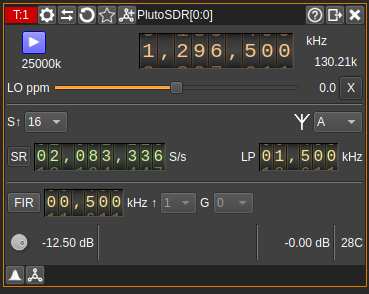
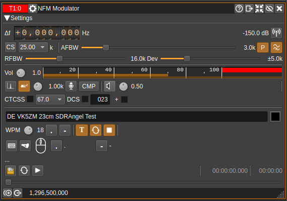
To prove that I could get this all working, I put the receiver on 1296.5MHz with the settings previously shown. I configured the transmitter slightly differently adding further decimation to reduce the effective bandwidth. You can see this below;
I then added a Narrow Band Modulator, by clicking the button just to the left of where “PlutoSDR[0:0]” appears in the menu bar (just like a channel button in a receive window) and selecting NFM Modulator from the drop down box. You then configure like so, based entirely on SignalsEverywhere’s YT video.
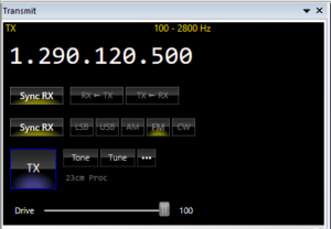
If you click on the purple button with the white triangle on the TX window, you should be greeted by CW being sent. Just so there was proof, I made and uploaded my own video.
In the above video the audio is being demodulated by the Icom R10 on 1296.5MHz NBFM just so that there was a “Real Radio (TM)” involved. The ADLAM Pluto is transmitting approximately 0dBm into a dummy load. The ADLAM Pluto receiver is displaying the received signal and waterfall, I didn’t bother with a channel/demodulator to listen to my own transmission, the R10 was doing a good enough job on it’s own.
So now that I’ve got that working, I can start to experiment with the ADLAM Pluto and some microwave multipliers to get me up into the higher bands. I also need to check it will still key the Pluto Charon kit and modify as necessary. More to this story shortly.
In my last post on the Pluto External PTT I had done some preliminary testing of the external PTT output using a multi-meter before wiring it to the Pluto Charon and confirming it worked. It was at this point things took a jump to the left and then a step to the right…
What I noticed is I would hit the TX button in SDR-Console and there would be a pause, one, two, three, then click would go the transmit receive (TRX) relay. Hmm that’s not going to do, a 3s delay between the PC software PTT and the Pluto Charon external amplifier ain’t going to work on FM/SSB.
However if I hit the TX button in SDR-Console again the TRX relay would click and go off without any delay. Now that was strange and the asymmetric nature of operation required further investigation.
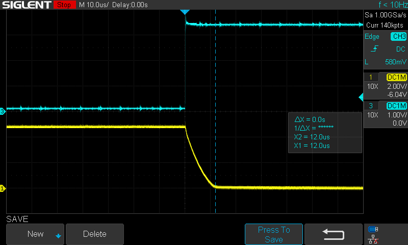
The first step was to rule out the hardware, so with a C.R.O on the Pluto Charon PTT line (connector A1) and another on the ADALM Pluto GPO0 pin (yellow and cyan respectively) we can check that the switching is nice and clean.
Nope nothing to see here, you can see the transistor on the Pluto Charon PTT board pulling the PTT line low and hitting zero volts in no more than 12us. Problem has to be elsewhere.
So now were into firmware and software territory, sigh this is going to be one of those rabbit holes.
I firstly tried the “for the brave” firmware that can be found on the Mini-kits support website, which is an early version of the PlutoDVB firmware. This changed the behavior entirely and there was a delay of 1-1.5s each time the external PTT changed state from ON to OFF. Not what I wanted, but better and perhaps more usable than the 3s ON and instant OFF I was seeing on the PlutoDVB revision 3.0.3 firmware + Rev C/D patch.
Further reading from the analog devices website suggested that the GPO pin connected my external PTT module could be controlled by some ENSM module within the AD9361-phy linux driver, so I tried some experiments with SDR-Console and the Analog Devices stock v0.38 firmware, that didn’t work either. It was clear that SDR-Console was not using this IIO method to switch the Pluto in to TX or RX.
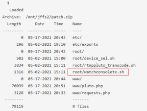
So I revisited the latest PlutoDVB firmware (perseverance 3.0.3 + Rev C/D patch) once again reading and watching more closely this time.
It was while applying the patch I saw something interesting, I’ve highlighted it in red adjacent. I wonder what that script does ?
The whole reason the patch was required in PlutoDVB Perseverance 3.0.3 firmware was to get the PTT working with revision C & D hardware. I wonder if that is where I start ?
So let me log into the Pluto and take a peek at the script.
#!/bin/sh
#https://www.analog.com/media/cn/technical-documentation/user-guides/AD9364_Register_Map_Reference_Manual_UG-672.pdf
source /root/device_sel.sh
ptton()
{
    #PTT on GPIO 0 AND GPIO 2 (GPIO 1 should be not touched)
    echo 0x27 0x50 > /sys/kernel/debug/iio/iio:device$dev/direct_reg_access
    mosquitto_pub -t plutodvb/status/tx -m true
}

pttoff()
{
    echo 0x27 0x00 > /sys/kernel/debug/iio/iio:device$dev/direct_reg_access
    mosquitto_pub -t plutodvb/status/tx -m false
}

echo manual_tx_quad > /sys/bus/iio/devices/iio:device$dev/calib_mode
#Manual GPIO
echo 0x26 0x10 > /sys/kernel/debug/iio/iio:device$dev/direct_reg_access
pttoff

while :
do
inotifywait -e modify /sys/bus/iio/devices/iio\:device$dev/out_voltage0_hardwaregain
gain=$(cat /sys/bus/iio/devices/iio:device$dev/out_voltage0_hardwaregain)
if [ "$gain" = "-40.000000 dB" ] ; then
    echo "SdrConsole PTT OFF"
    pttoff
else
    if [ "$gain" = "0.000000 dB" ] ; then
        sleep 2
        gain=$(cat /sys/bus/iio/devices/iio:device$dev/out_voltage0_hardwaregain)
        if [ "$gain" = "0.000000 dB" ] ; then
            echo "SdrConsole Power Max PTT ON"
            ptton
        fi
        else
            echo "SdrConsole PTT ON"
            ptton
        fi
    fi
done
So reading my way through this script by the time I hit line 24 I had confirmed
SDR-Console does not use the ENSM module within the Pluto ad9361-phy driver
Instead the script uses the sysfs subsystem to read different values from the IIO driver
SDR-Console varies the TX gain within the IIO driver between two limits that the script interprets and drives the relevant GPO pin
In an attempt to prevent a race condition, line 31 introduces a 2s sleep function between successive reads of the gain value
Guess where the 3s delay I’ve been searching for comes from !?!
So a quick bit of hacking on this script, changing line 31 to read “sleep 0.1” or 100ms, then restarting the “watchconsoletx.sh” process increased the speed of the external PTT to the point where the delay between SDR-Console and the TRX relay on the Pluto Charon activating is nearly imperceptible. I’m not sure if using a fraction of one second is valid in this shell, it may have been ignoring it, but it proved my point.
However what I’ve done to this script and the way in which SDR-Console works I’m not convinced will work 100% of the time. The other problem is any changes that are made to these script files are not permanent they are only kept in RAM, so as soon as you reboot they revert to those stored in volatile memory (flash).
So it looks like I may have to reverse engineer the “pluto.frm” file and see if I can hack together a better script to make this work how I want. At least I now know where the 3s delay has come from and that there are possibilities to fix it.
That however will have to wait until the next post.
The next step in the process of using the ADALM Pluto is sorting out a press-to-talk output to drive the Pluto Charon. In this instance I’ve followed the tried and trodden path of adding a small transistor output to one of the GPIO pins and updating the firmware. There are some interesting articles on the ADI website that discuss how to do this via the FPGA, but I decided to learn to walk before I ran.
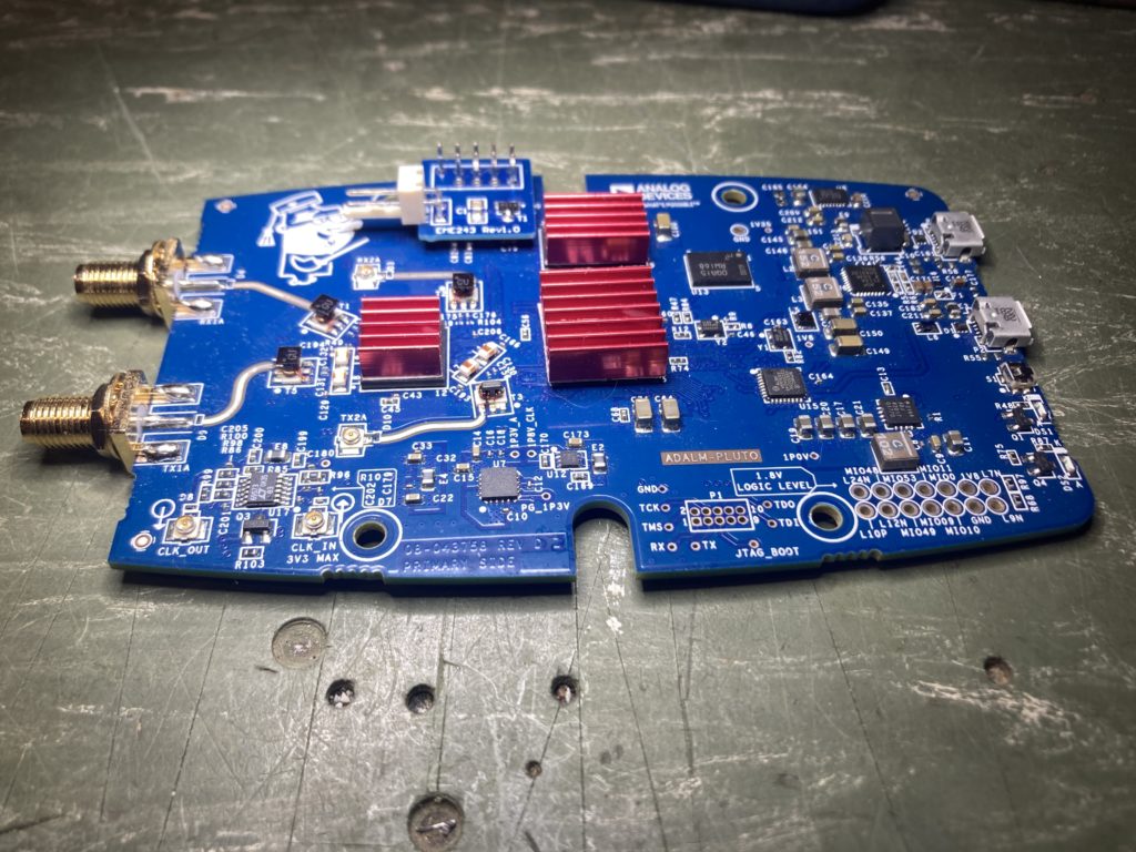
When I ordered my Pluto Charon kit I also purchased the separate PTT module which you can see here (click). This is very easy to install, just make sure you observe good ESD practices when you remove the Pluto from it’s case and handle it on the bench.
Here’s the photo’s of how I installed mine.
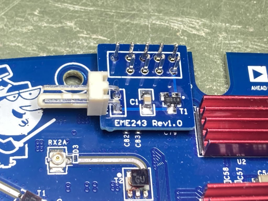
I decided to use a small two pin right angle KK 0.254″ molex connector for the PTT output, as I’d like the capability of unplugging Pluto and Charon boards for service/changes/updates etc.
Now for the hairy scary part of the process. On the Mini-kits website is a URL to some custom firmware written by Evariste F5OEO that can enable a PTT function on a GPIO pin. I was at first a little alarmed by the comment “for the brave”, but it turns out this firmware is part of the PlutoDVB project. You can find later software from 2022 on Christian F5UII’s website (click) and you’ll see some comments about fixing the PTT on the Pluto Rev D boards to work with the latest versions of SDR-Console. I have a Pluto Rev C, which is the same as the Pluto Rev D, so I had no choice but to use this newer firmware and work out what to download.
So after reading most of Christians Website I discovered I had to do two things. Firstly I had to swap from the official ADI Pluto v0.38 firmware to the custom PlutoDVB 3.0.3 firmware. Secondly patch the 3.0.3 firmware to account for the Rev D hardware. This wasn’t obvious where to start.
Below is a summary of the steps I used to swap the firmware.
Connected the Pluto to my PC, checked it had presented a removable drive
Download the firmware from Christian F5UII”s website, I used the PlutoDVB perseverance firmware 0303 (26.6M)
Extracted the pluto.frm from the downloaded zip and stored it on the Pluto removable drive created on my PC (don’t get confused or alarmed by the file name “patch.zip” as this is indeed the entire firmware)
Ejected the Pluto and waited for it to finish doing the upgrade and reboot, once done it reconnected to the PC
Used a web-browser to point to http://192.168.2.1/index.html, confirmed it presented the “Lets go to PlutoDVB” welcome screen, not the ADI reference material.
Then clicked on the “Lets go to PlutoDVB (USB connection)” button which launched into the system setup.php page
From the menu across the top, selected “System ” then “Maintenance” where I found the patching and upgrading firmware mechanism.
For my hardware (Rev C/D) I needed to download and apply the “Patch for PlutoSDR Rev. D hardware”
Applied the patch, saw that within the “Delete Patch” window the updated files were displayed once done
Success !
Now I could configure the PlutoDVB firmware to do what I wanted, which in my case was to use SDR-Console. So from the “system” menu at the top I clicked on the “Pass-through” option and hit apply. That should be all I needed to complete.
There is an error message displayed across the top of the screen about a datv text file not being present. If you enter your call-sign in the respective field on the setup page and your name in the DVB provider field, hit “apply settings” and this will create the right file and the error message disappears.
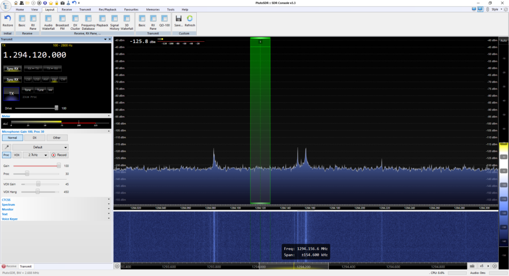
Once all of this was done, I was able to setup and configure SDR-Console and test that the PTT worked with a multi-meter. Below you can see SDR-Console listening on 23cm ready for me to hit the TX button. The Pluto is sitting right up against the PC, so I’m not surprised there are some birdies in the shack, I’ll only panic once the Pluto and Charon and boxed up together.
For my next trick I intend to hook this up to my CRO and see how long before or after the PTT line is asserted does RF appear at the transmit port. However that will have to wait for the next post.
For the past couple of weeks I’ve been giving some thought as to how I’d box up the Mini-kits Pluto Charon. As with any problem the first step it to work out how I want to use it.
I’d like to be able to use the Pluto Charon both in the field and in the ham shack. The ADLAM Pluto connects to a PC via a micro USB and presents itself as a USB Ethernet device.
Further reading suggests that the ADLAM Pluto USB OTG port can host an external USB-Ethernet adapter or USB-WiFi adapter, making it possible to un-tether the Pluto from a PC or use standard IT infrastructure. In my situation an external Ethernet port is of interest, since I could easily build all of the Mini-Kits Pluto boards into their own enclosure and simply network them together and into the same PC without having to count on multiple USB ports. This again fits with my field and shack mode of operation.
The output power of the Mini-kits Pluto Charon, Pluto Styx and proposed Pluto Nix kit is in the region of one to two watts. This is more than enough transmit power to jump from hilltop to hilltop over quite a path with some antenna gain and short cables. If however you want to lift the antennas up to the top of mast, external in-line amplifiers up behind the antennas would be required to keep losses under control. If the external amplifiers also included a separate mast head amplifier, then losses of up to 6-8dB at any of these microwave frequencies could be accommodated without significantly impacting performance. I’ll be exploring this further once the first Pluto Charon kit is completed.
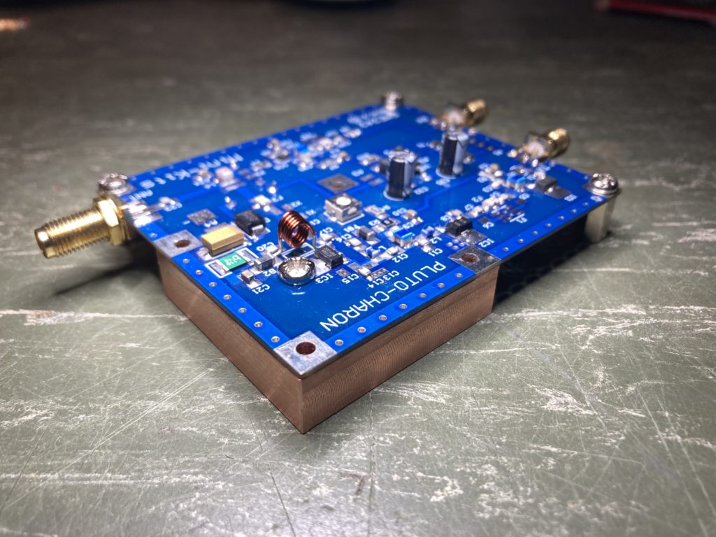
So, the first step of course is to get the Pluto Charon kit operational, to do that I needed to test it. The kit came with a small 40x40mm heatsink that I could attach to dissipate the heat from the final amplifier IC1. I mulled this over for a while before deciding I’d prefer to put a much larger heatsink on the top of a die cast box and mount the Pluto Charon to that. A good example of what I’m thinking is how I built my Rubidium reference (here). My main reasoning is I’d like to stabilise the heat within the die cast box so the Pluto does not need to work so hard on keeping the frequency stable. Did I mention the Rubidium reference, one would say this started these shenanigans.
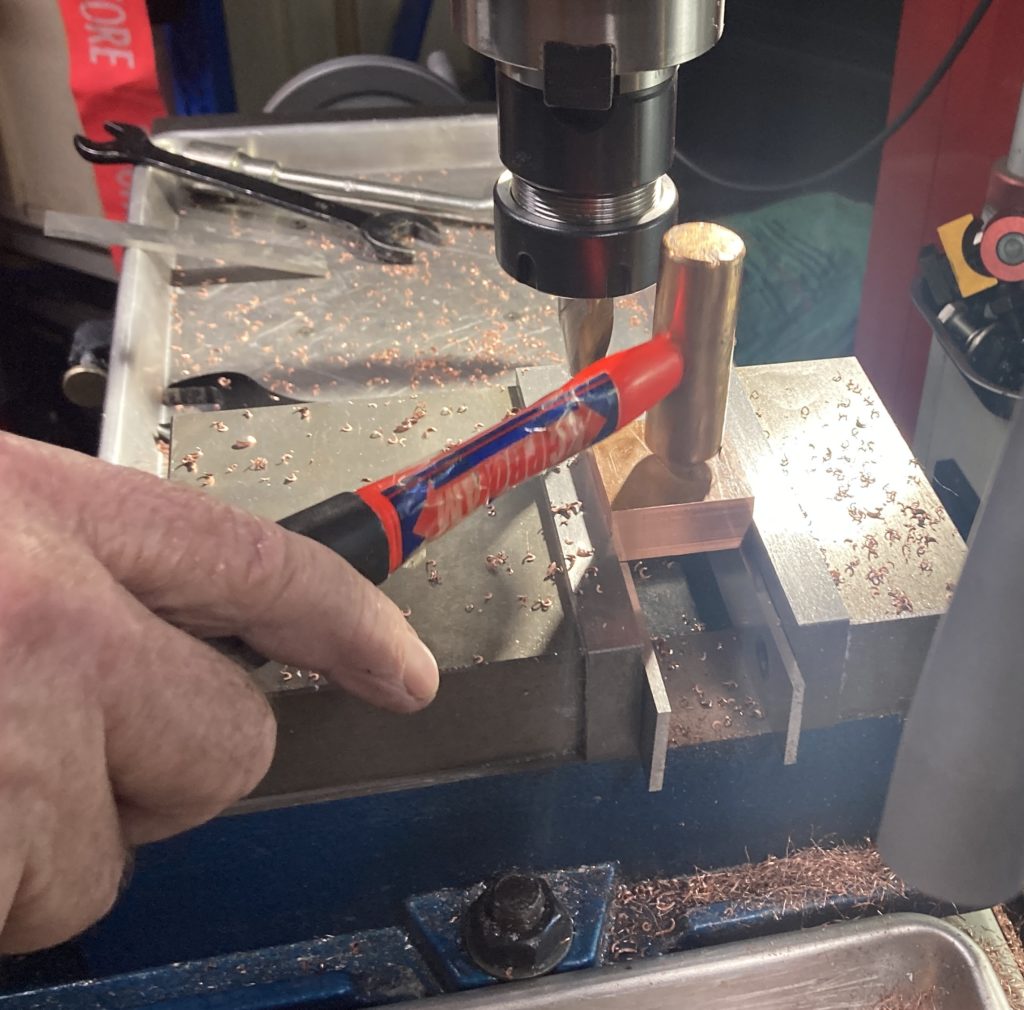
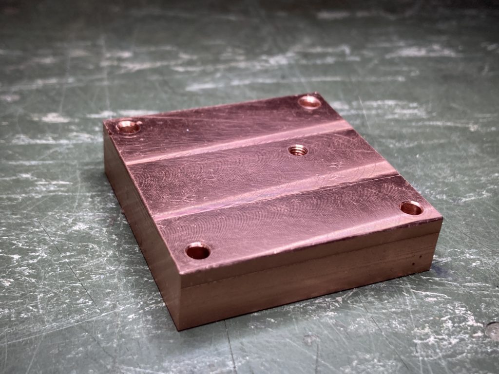
To get the heat out of the Pluto Charon final amplifier the layout dictated a small copper block to be made. There are components on the top and bottom of this board, so one needs to pay attention to clearances etc. So it was off to see a good friend with a lathe ;thanks Peter it was a fun afternoon and some good machining Zen !
Tappy tap tap !Finished Copper BlockInstalled
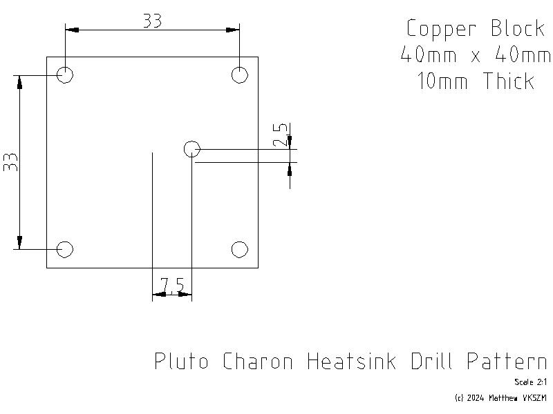
It is no coincidence that the copper block is 10mm thick, this is perfect for three 10mm hexagonal spacers to be placed under the remaining three sides of the PCB for support.
The hole in the middle of the copper block is what transfers the heat from IC1, so this was tapped to accept a M3 hole. The PCB had a plated 2.5mm hole and was reamed out slightly to accept the larger M3 screw. The M3 screw used was tin plated copper, not tin plated steel/stainless which is a poor conductor of heat.
The remaining four holes in the PCB that hold the heatsink were left M2.5 and the holes through the copper block drilled 3mm for clearance. When this is attached to the heatsink, four M2.5 x16mm screws through these holes in the heatsink, washers and split washers will be used to sandwich the assembly and keep everything held tight.
So I don’t forget and for anyone following along at home I’ve included the drill pattern. This was the only information conspicuously absent from the assembly instructions. This drawing is drawn from the top of the PCB looking down. The hole in the middle of the heatsink is referenced from the center of the copper block. For some reason I can’t get LibreCAD to show a mark for the origin yet. I hate having to measure PCB’s to get hole locations, a combination of transfer punches, vernier calipers and gauge pins were used to establish and check that these locations were close enough.
Now it’s time to carry on with the Testing and Alignment of the Pluto Charon !
For quite some time I’ve been promising my eldest son his own bedroom. However like everything, this is somewhat complicated and has taken far longer than expected. To make this happen, I’ve had to make more shelving in the shed, move stuff stored in the garage out into the shed, clean out the garage and move my office, which was in the 3rd bedroom of the house out into the garage soon to become my new man-cave. I’ve felt like I’ve been playing musical chairs with storage boxes for quite some time. Then there is the time required to renovate said 3rd bedroom back into a teenagers retreat, so much work, so many weekends, I still hate painting.
However, while moving things out of the office and into the new man-cave I rediscovered the Pluto Charon kit, languishing in a forgotten project box. My original plan was to use this kit as my 23cm home station, however during the above renovations a member of my radio club offered me a pristine Icom IC-910H with 23cm module which I couldn’t refuse. Needless to say the Pluto Charon priority and urgency was pushed back somewhat.
Fast forward two years and having rediscovering this kit, along with seeing the new 12cm Pluto Styx kit available (click) and a teaser for the 6cm Pluto Nix, well it was time to finish it and continue working my way up through the microwave bands.
This kit requires the usual SMD microwave construction techniques, so fine solder a good iron, a steady hand and optical magnification is an absolute must. The Mini-kits instructions and support page are as usual first class. However one should heed the warning on the website ordering page that “this kit is not for beginners and requires very experienced soldering skills”.
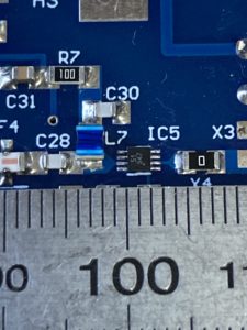
I generally found the majority of the kit straightforward, until I got to IC5 which is a BGU8051 preamp from NXP. You should check out it’s specs on the NXP website. This is one of those “looks big on the computer screen” kind of parts that even designers get caught out with when ordering their first samples. I’ve included a photo, along with a strategically placed steel ruler for scale. That IC is tiny… really tiny !!!
At just two by two by three-quarters of a millimeter with eight pins, it was clear that this was not going to be soldered by any ordinary soldering iron. Thankfully I have a hot-air rework station, so I manually pasted the board with an I-Extruder, used plenty of flux and re-flow soldered the device to the board. Since inductor L7, capacitor C30 and resistor X3 were so close, I chose to leave these off until I had soldered IC5 to give me room and ensure the hot air did not cause unnecessary stress to adjacent components, YMMV. I also typically use a T3 solder paste for the majority of my kit building, but for this board I resorted to using T4 since you could nearly count the number of solder balls dispensed onto each pad of IC5. However I’m happy with the result and with the right tools this kit can be assembled at home. There are many YouTube tutorials on how to solder with hot-air worth watching as well.
Once I had the kit soldered together I then turned my attention to how I was going to put it in a box and begin to test it. However that is for the next post !
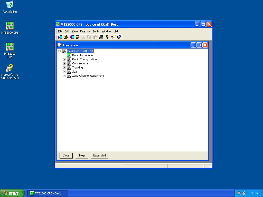
It is no secret that Motorola CPS software does not like to run on modern operating systems. I still have a number of UHF Motorola MTS2000 handhelds which once given new batteries have proven themselves useful time and time again.
However my trusty old Windows XP laptop, with a real serial port fried its motherboard recently never to boot again. My immediate thought was “yikes what do I use now to program these Motorola radios” ?
So rather than go looking for further ancient hardware I started experimenting if Motorola CPS would run on a Windows 10 64-bit platform. I’ll spare you the gory details, but no amount of compatibility mode twiddling or research would result in a working system. There is something fundamental in the RS232 32-bit sub-system within the CPS software that prevents this from ever working. I could not get the CPS software to “read device” instead receiving a timeout. Grrrr….
So the only alternative was to experiment with an older version of Windows in a virtual machine and passing through a serial port. I remember when Windows 7 was first released Microsoft released a version of Windows XP that would run within Microsoft Virtual PC. The Motorola CPS software is from around the same time, so it was an ideal candidate to try. Turns out this was easier than I expected.
Setup Windows XP Virtual Machine
I found the following setup guide very useful from Help Desk Geek website (click). The download link from the Microsoft site has disappeared, but the alternative link from the CNET site was working at the time of this post.
I followed this guide closely, there are a few steps you needed to pay attention too but otherwise this went smoothly. I’m currently using a Windows 10 host and the only trouble I had was with the mouse, where I could not control the mouse within the Guest correctly, but you can temporarily disable the VirtualBox “mouse integration” feature to get around this until the VirtualBox Guest Additions are installed. Once the Guest additions were installed, everything worked as expected.
Activating Windows XP in 2022
The next challenge is since Windows XP support ended there is no way to “activate” this vanilla of windows any more which is right painful. One work around is to snapshot the VM and rollback each time you wish to use it, I wasn’t a fan. So thankfully the “Roger Webb” YouTube channel had a video that shows how to work around this problem, don’t forget to leave a like.
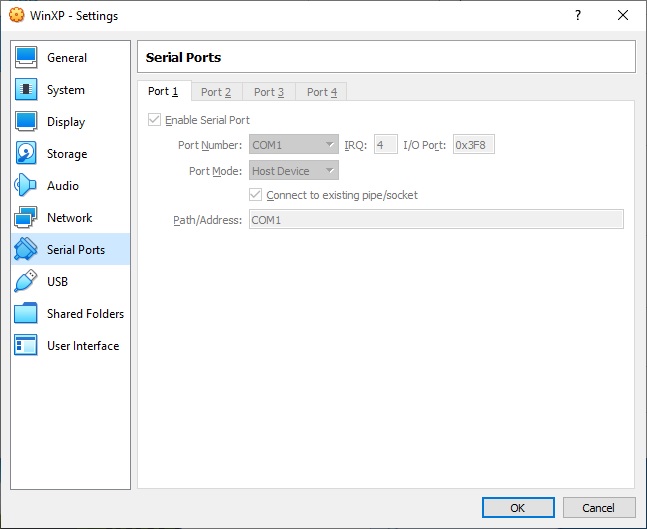
Serial Port Pass Through
Now I’m lucky that my Gen-3 I7 desktop machine has a real serial port on the motherboard. This was one of the very last Intel made motherboards with the legacy IO chipset, so not only do I have a serial port it has a parallel port too.
To allow Windows XP access to the host serial port, one just needs to configure the hardware pass through. Within the VirtualBox settings there is a separate “Serial Port” tab that simply requires mapping between the guest and host systems.
As you can see I’ve simply mapped COM1 on the guest to COM1 on the host, simples !
Copying Motorola CPS into Windows XP
So for the grand finale we can install the Motorola CPS software within Windows XP. How one gets the software installed can be done a few different ways.
I decided to use the VirtualBox shared folders mechanism. With the guest additions installed I found once I’d configured the shared folders they were automatically mapped as a network drive the next time I restarted the Windows XP guest. It was a simple matter to then double click the executable and install.
There were a few websites with rough instructions, but I found after watching the following YouTube video from Peter Downie I was able to get it working in short order;
The other method I’ve used to pass software through to a guest is to use a USB thumb drive. Copy the files from the host to the USB, pass the USB through to the guest, move the files and eject to pass it back. Both methods work just as well as each other.
The Proof is in the Pudding
So once you can copy the relevant files into the VM, then it’s a simple matter to install and run the Motorola CPS software. Then simply configure it to talk to the serial port you’ve passed through which is COM1 in my case, then try to read a physical radio. Please note that Motorola CPS software is licensed and cost real $$$ to purchase, please do not request copies of said software fro me as refusal often offends.
You will know you’ve got it right when you hear the radio beep, it says PRGM on the radio display and you are greeted with the contents of your code plug.
I was certainly relieved to be greeted with the screen shown above, make my changes and write the config back to the radio. I’m once again in business. I hope that other users of older Motorola CPS software find this useful.
I was recently looking at getting some radio gear that would get me up onto the Australian 23cm Amateur Radio Band. My first thoughts was to find some second hand commercial amateur gear, but this was soon dashed when 20 year old radios on eBay were fetching more than A$1000 in less than pristine condition. They are hard to find !
My second thought was of course a transverter. Where I would take one of my 2m or 70cm transceivers and “up-convert” the output onto the 23cm band. This is usually done by a combination of loads, mixers, fixed oscillators and amplifiers that you buy assembled or as a kit. Since I wanted to do both FM and SSB this presented something of a problem as the receive transmit frequency split for Australian 23cm repeaters is +20MHz. This means the radio attached to the transverter IF port has to be capable of wide band receive, which is not very common. So my calculator again suggested after I’d built a transverter, added a dedicated IF radio I’d be somewhere northwards of A$750… sigh that second hand commercial radio looked good again.
One of my local radio club members then introduced me to the Analog devices ADALM-Pluto SDR and the Pluto Charon 23cm module from Minikits here in Adelaide. I was hooked and two new toys were duly ordered and shipped. The cost of both the ADALM Pluto and Charon 23cm module was less than A$450 delivered but I did have to do a little shopping around to get the Pluto at a good price.
I then started researching what exactly you can do with one of these little devices and what exactly I’d just bought. I’m simply amazed at what Analog Devices have stuffed into this little box, better yet I’d received one of the Rev D platforms which has all the bells and whistles. As I discover things about the Pluto, I’m sure to blog them here soon.
I was again pleased to find the ADALM-Pluto was already supported by SDR-Console written by Simon Brown G4ELI. I’ve used SDR Console for many years in all of my HF contesting stations to display waterfall information. Using it for transmit was going to be a new experience.
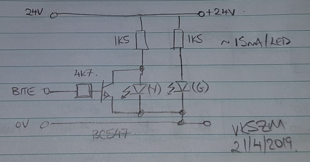
The Efratom LPRO-101 has a Built in Test Equipment (BITE) signal available on Pin 6. This pin is connected to the 5V logic within the module. When the BITE signal goes LOW (0V) then the physics engine has achieved lock within roughly +/-5×10-8 of it’s absolute frequency. Thankfully it can do this within 3-4 minutes of operation.
When I’m out in the field it is certainly useful to know what the reference is doing or if something has gone wrong without having to pull it apart and get out a multimeter. So on the front panel I’ve placed two LEDs one for power and the second to show lock.
The lock signal will be nothing more than the BITE signal inverted, which can be done with one transistor. I’ve seen some quite elaborate two and three transistor circuits, but we only really need one. The circuit I’ve draw below is straight out of my engineering log book, it’s so simple I couldn’t be bothered firing up Altium to draw it;
Basically we use one transistor to shunt the LED so that it is OFF while the BITE signal is HIGH. There is no rocket science here. With the heaters in the reference drawing 1.2A at startup throwing an additional 15mA through a transistor until it’s locked should be no big deal. The entire current drawn is approx 30mA, they are certainly bright enough in daylight, they might require turning down after using this at night, time will tell.
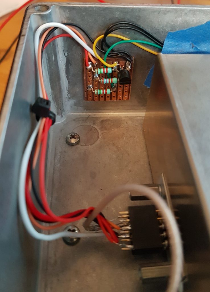
The circuit above is so simple I built it dead bug style on a piece of vero board. I did this so I could simply use double sided tape to hold it to the box and not short anything out.
One minor annoyance I’ve found is at the time power is applied the BITE output remains LOW for half a second or more before it goes HIGH. This means that the locked LED will light momentarily, then go out for 3-4 minutes as the reference warms before it lights again. The video below shows what I mean, for such a simple circuit I’m happy to put up with this feature;
You can hear the first click of the power supply, the Locked LED will light and go back out again. This was done when the reference was already warm so it takes less than 20s to regain lock again.
Anyway I’m certainly pleased with the simplicity. However now I’ve got ideas to use a micro a DAC and give this thing some intelligence. More notes in the log book for when I find time to come back to this again, for now it’s time to get out in the field and use it in anger !
It can take a GPS disciplined oscillator a while to stabilise and settle down. When I first tested my new free running rubidium reference the GPS disciplined rubidium reference had spent no more than an hour making it’s observations and corrections. So I left it running over night with the intention of measuring things again in the morning.
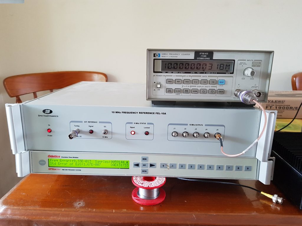
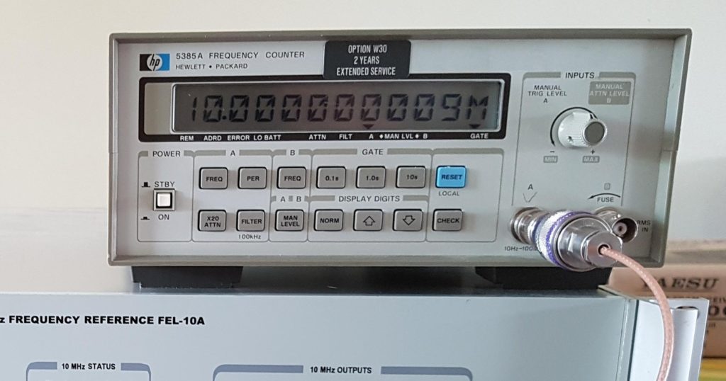
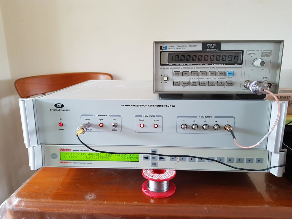
So after 16 hours the frequency error has reduced more than three decades, should be good to go. I also have a precision TXCO reference (SDI FEL-10A) so I thought I’d measure this first and see what sort of stability and accuracy this can achieve. Both the free running TXCO and Rubidium were switched on 30 minutes and left to stabilise before measurements were made;
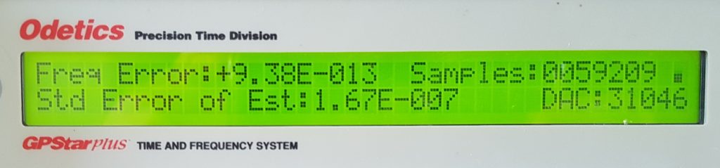
So that is quite a respectable result, being within +0.318Hz of our 10MHz target. Then for the main event it was time to re-measure the free running rubidium;
So this is a little higher that what was measured last night, but +0.009Hz or +9mHz is still a great result. To put this into perspective if I were to use this reference to lock a series of transverters this is the final frequency accuracy I would expect;
I think if I were to go higher than 70cm then a GPS disciplined oscillator is in order (there is a Trimble Thunderbolt in a box somewhere), at least I have some idea now what the upper workable limit is. One of these days I may yet get in and tweak the external C-Field input and see if I can tighten this frequency error up a little, that will have to wait for a 12-digit counter.
The free running TXCO also has a reference input so for a laugh I attached the free running Rubidium to the TXCO and waited to see what happened. The lock LED lit pretty much instantaneously and the result was;
Exactly the same as the Rubidium on it’s own. What I do like about the TXCO is the 6 channel output with >120dB of isolation between channels. At least now I have some idea how stable this oscillator is, so now I can start thinking about what I’ll do with it.