Curse of the Black Pearl, Err wires…

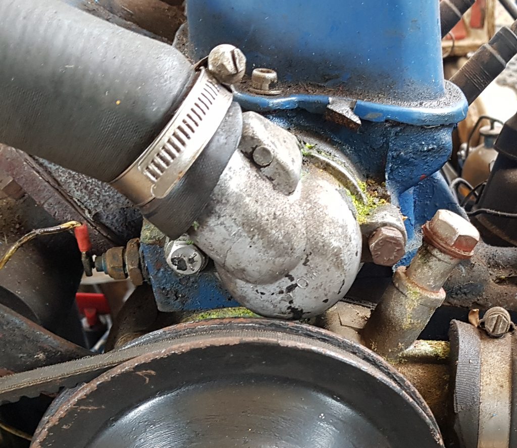
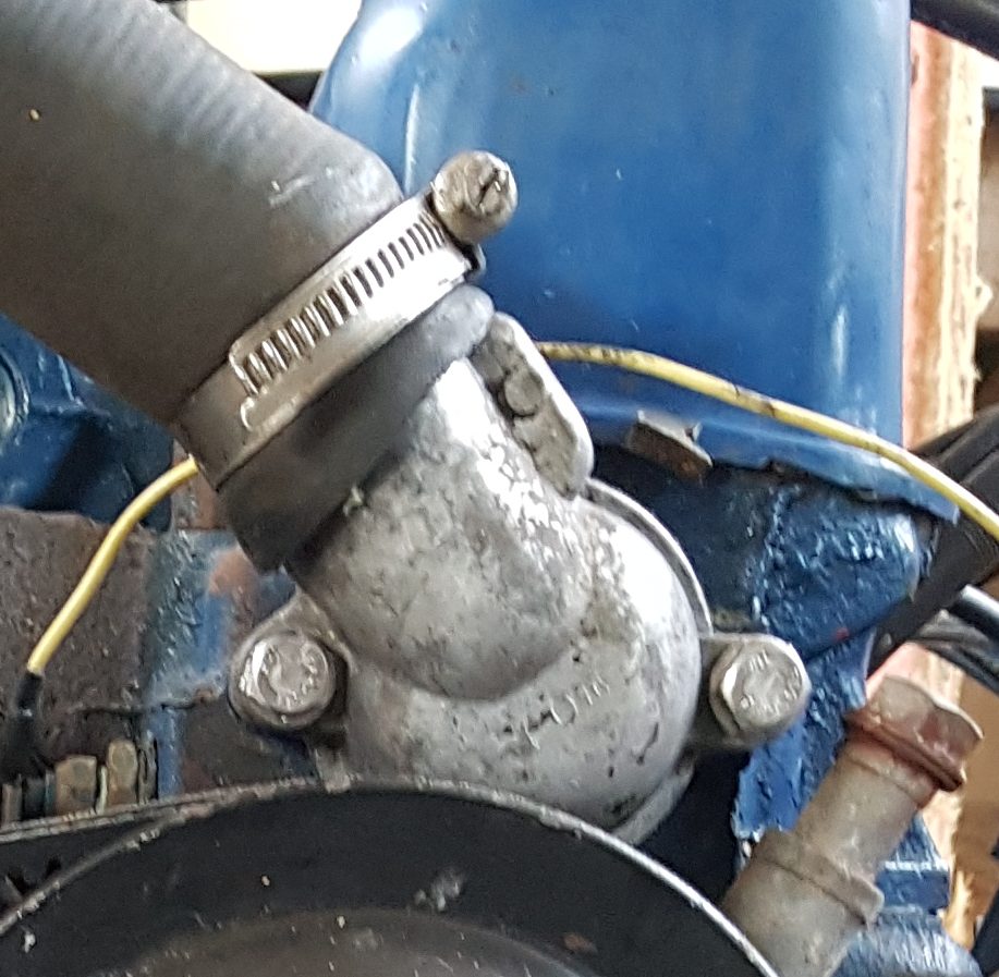
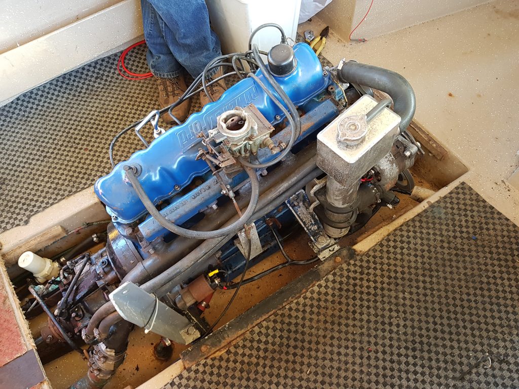
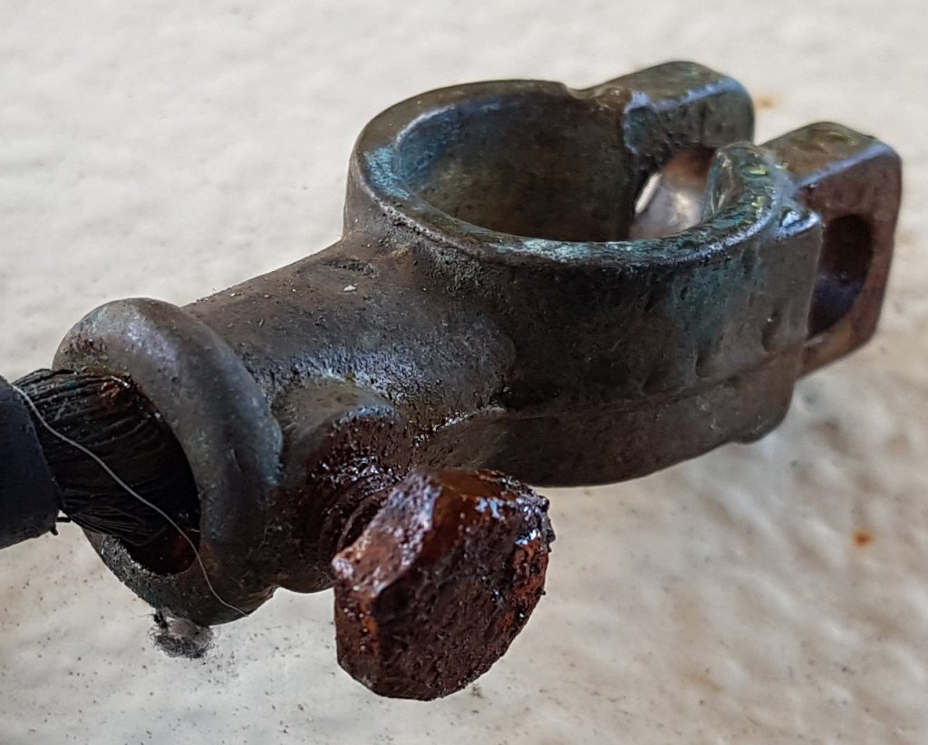
Having serviced and re-furbished a good portion of the engine and accessories I had one more small trivial, quick task to perform. That was to replace some very manky looking battery terminals. So out with the beak nosed cutters, lop the terminal off, strip back the wire to reveal, the copper wires were all black. Oh dear it was going to be one of “those” days.

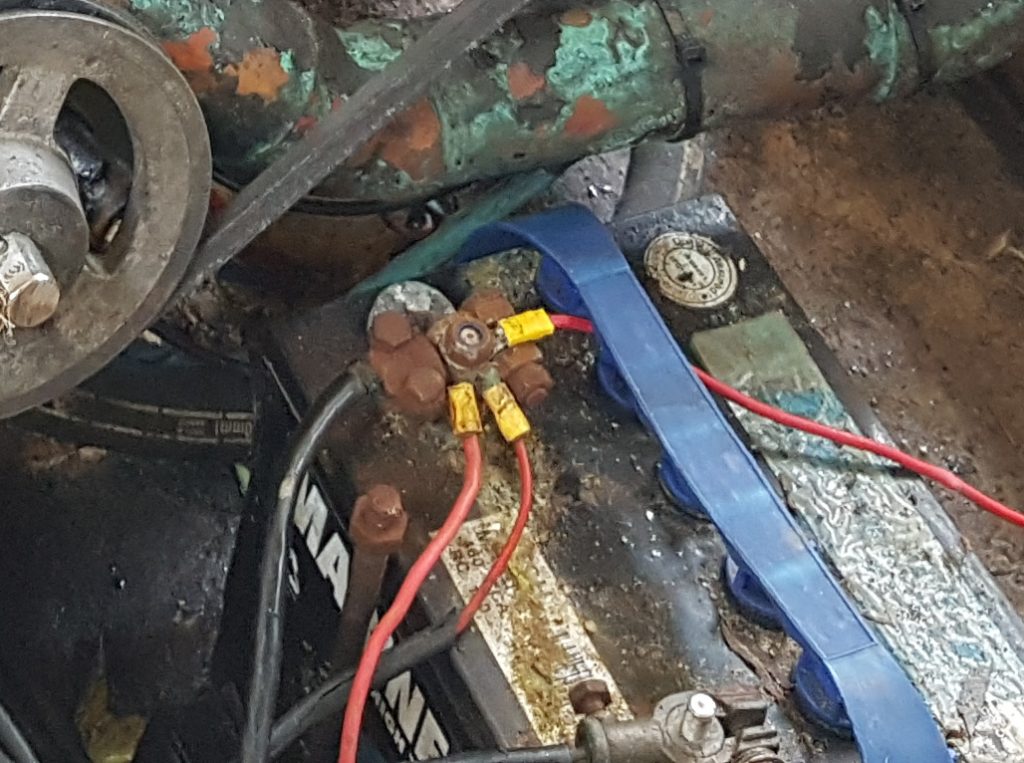
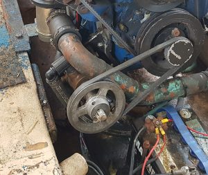
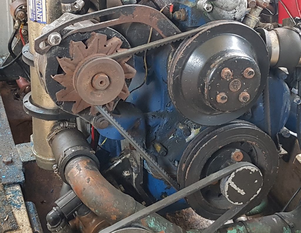
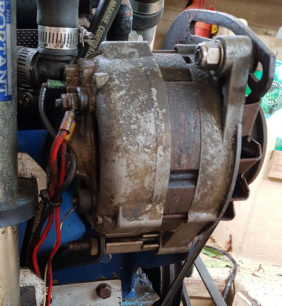
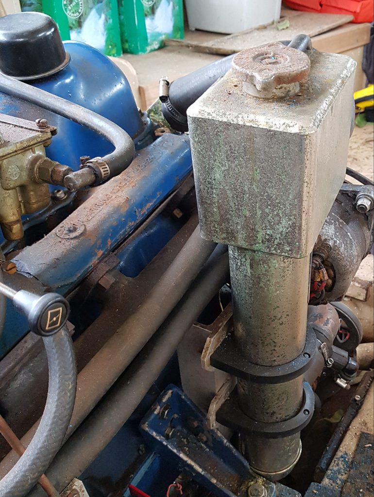
The picture above shows the very manky looking battery terminals and the original orientation of the battery. For reference the terminal in the top of the image is the battery positive, the copper pipe above it is the cold water side of the heat exchanger, err yes that is technically earthed and the battery un-restrained. There is no way we could leave it like that.

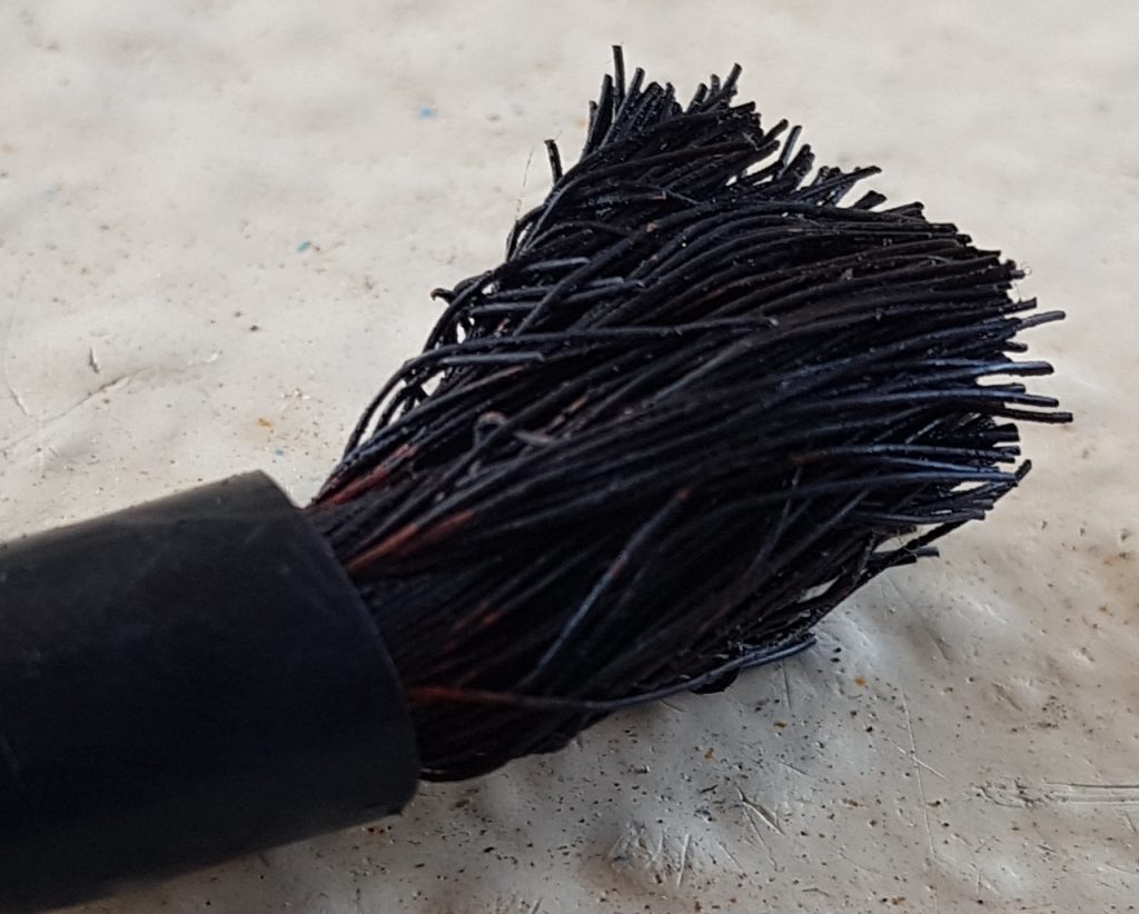
So getting back to the wiring, at some point in this poor boats life it had been wired up with standard automotive copper wiring. Now for the majority of the time this is fine in cars and perhaps houses, but in marine environments where corrosion is rife this is a recipe for disaster. The black manky looking stuff is actually a form of copper oxide which is non-conductive and hard to remove. Once it starts to form it doesn’t stop until every strand along the entire length of (and within) the cable has oxidised as well. The worst part is the wires were to the starter motor which relies on a very low impedance.

Thankfully there is a local Jaycar electronics store around the comer that caters to the “Doof Doof” car audio community. This car audio community seems to like big high power amplifiers that use too much gold plating (IMHO) on their connectors and fuse blocks, but it does however mean they stock marine grade Tinned Copper wire in useful sizes from 14 gauge through to 4 gauge in both Red and Black. Better yet it is fine stranded with a soft silicon durable sheath making it very flexible and a pleasure to work with. Below are the ones that I like to work with, hopefully the part numbers out live any URL changes that may occur on the Jaycar site;

If you haven’t already found self sealing automotive crimp terminals I suggest you wander off and google these too I’d never seen one until I stumbled across them on one of my YouTube feeds, a big thanks to Damien & Jess from Project Brupeg for putting me onto these when they wired their wheel house. There are also nice kits you can get from eBay for reasonable prices. This type of connector once crimped, you hit with the heat gun and they shrink and seal the end of the connector. It certainly saves a heap of time not having to cut and use a separate small piece of glued heat shrink. Better yet you can see the internals with the heatshrink being semi-transparent, which means if they corrode you’ll find out before it’s too late.

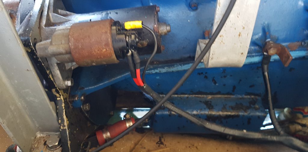
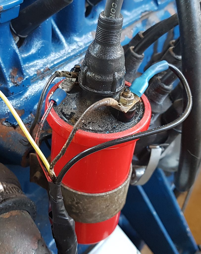
So once armed with cable, connectors and a few roles of Electrical tape it was time to start cutting wires to find the extent of the black wire syndrome. Needless to say I ended up rewiring the entire engine bay, from battery to starter motor, alternator to battery and the remaining Kettering ignition system.

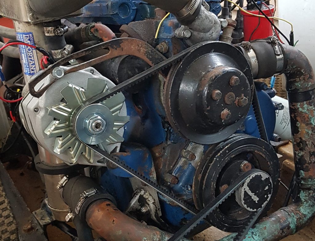
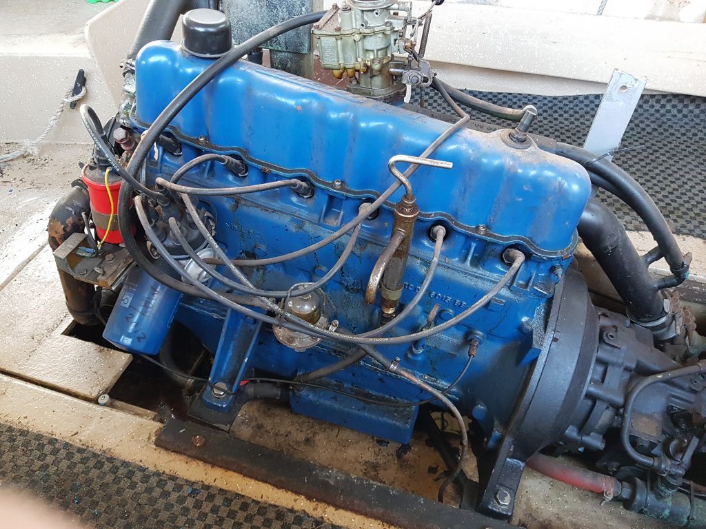
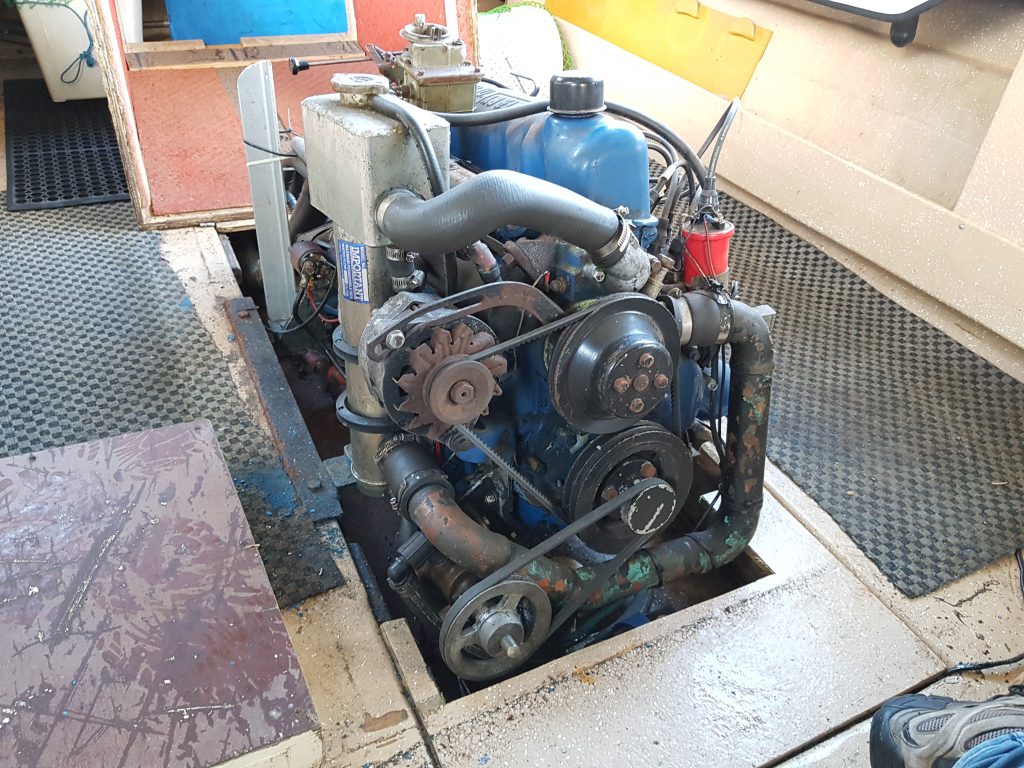
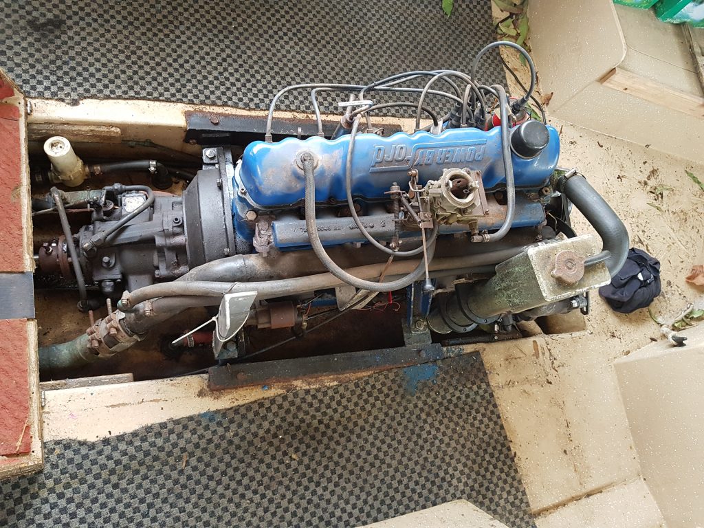
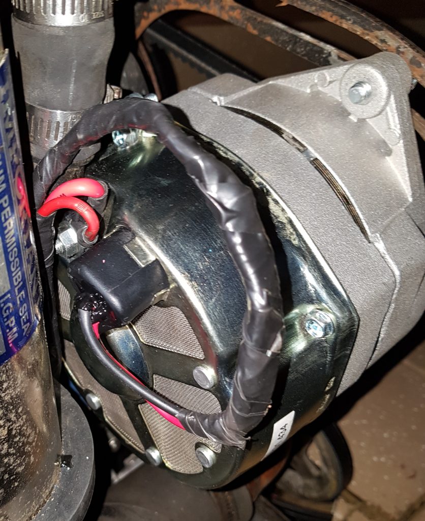
I was thankful that the wiring between the engine and gauges while not tinned had not suffered anywhere near the same level of corrosion. So I stopped here noting that at some time soon I’ll be up under the dash re-wiring this as well. So the proof is in the pudding, here’s a few photos of the completed work.

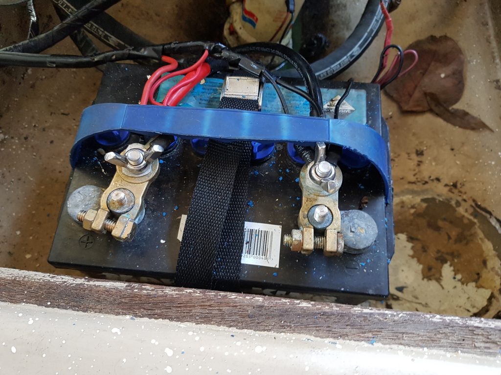
You may also notice that I’ve turned the battery through 270 degrees so that the terminals now face the bow of the boat. This puts as much distance between the battery terminals and the engine and accessories as possible. Directly underneath the battery is a false floor where I should be able to screw a hold down strap to secure the battery in place. Not forgetting to seal the screws since this is a wet bilge. Unfortunately the cover that goes over the battery no longer fits, it’s pretty clear why the previous owner had rotated the battery to where I found it. We don’t technically walk where the battery sits, so I’m thinking of raising up the floor here just an inch to clear the terminals. I’ll do this when I make a new engine cover.

Changing the Raw Water Impeller

During the first sea trials of my Nereus at wide open throttle (WOT) it would slowly overheat with the coolant temperature rising from 85-ish degrees up over 100 degrees celcius. If I slowed down and dropped the revs the temperature would again slowly go back down. So either the cooling system was not quite able to pump enough raw water through the heat exchanger or the engine is producing too much heat. I certainly know that the heat exchanger is not blocked since it had been serviced recently.

When purchasing the boat the original owner had told us he’d changed the raw water impeller “a couple of years ago” so I’d purchased a spare impeller but not bothered to change it. The pump is right at the bottom of the engine in the bilge, so it’s a bit of a pain to get too which might also contribute to why it had not been changed.

Anyway I’d run the engine for about an hour on tap (towns) water but only at or just above idle, not under heavy load. So I decided to change the pump for peace of mind. A quick check on the internet and there was a YouTube video from 350vic that gave me some clues as to what was necessary, it didn’t look that hard.

Famous last words.

So first I had to get the pump out of the boat an supported by something that would make it easy to work on. Getting this pump out of the boat was as hard as I feared. There is not quite enough adjustment on the belt tension bolt to allow the belts to slip on and off the pulleys, in fact it hits the sump and if you’re not careful you can punch a hole in it. The bolts that support the lateral load of the pump and hold it in place you just can’t get a ring spanner on, so you have to feel for them using an open ended spanner and shift them a hairs breath, flip spanner, shift, flip spanner. If you’ve ever been forced to do this you will know how slow it is to back the bolt out just half a turn to loosen things off. With a few minor changes to bolt locations this could have been easily serviceable, oh well I do like a good project.

So after a good hour of extraction I managed to get the pump out an into a vice for support, here’s a series of shots that shows the pump being supported, the rear cover having been removed. The impeller didn’t look that bad, there’s a bit of wear on the rear of the vanes but there were no missing vanes and the pump wasn’t hard.

I’m not a fan of using the two screw drivers method for impeller extraction, bruising the face of the pump is just a no no. So for my first time I used vice grips and a slide hammer, being careful not to loose the bronze Woodroffe key. I will certainly be looking at a set of impeller pullers when I have some spare funds in the bank.

Above you can see the backing plate and Woodroffe key, along side the pump housing with the new impeller ready to go back in. So what they don’t tell you about re-assembling these pumps is you’ve got to bend the vanes of the new impeller, while inserting the impeller into the housing, which is offset to one side AND you need to catch the Woodroffe key in one movement. Oh and if you’re supporting the pump in a vice, then make sure the front of the pump is chocked otherwise everything tries to run away.

Needless to say it took me four attempts and a coffee after two to settle my frustration before I managed to get everything aligned and the pump re-assembled. After the first attempt I also marked the Woodroffe key location on the back of the shaft and the impeller so I had a chance of keeping them aligned. It certainly helped to dob a bit of grease on the back of the Woodroffe key and make sure the front edge was slightly down, but not too far down or it would then force the key down and lock it against the pump wall. Sigh.

To prevent the pump running dry I also lubricated the pump walls with a little marine clear grease, I see on some forums people use silicon spray or lanolin, YMMV.

Hooray ! There’s the proof that I did get it back together and didn’t just go and buy a new pump out of frustration. I also dobbed a little “never seize” on the threads of the screws so it should come apart again in a year or so.

It was then just a matter of putting it back into the boat, reversing the disassembly process. Reminding me again why I need to replace the pump mounting assembly.

First Sea Trials

It’s never a good idea to go and place a new boat in the wire and head off into the blue yonder and not expect problems. So to keep things simple I arranged a couple of mates to help and dropped the Nereus into the North Arm of the Port River.

So far so good, it floats ! You’ll have to excuse the state of the pontoon, the local Pelicans have made it their preferred home during the Winter. Once in the water the obligatory “is water coming in” checks were done, it certainly did not have to go back on the trailer.

There was nothing left but to go for it and take things easy. So while cruising slowly towards the Port River the steering and gearbox (ie reverse) were checked, along with lights, bilge pump and the fish finder. Here’s a video of us just pulling away from the pontoon in the obligatory 4 knot zone coming out of the North Arm,.

Once clear of the North Arm we could then head towards Outer Harbour with a bit more power on keeping within the 7 knot limit. During this time we were watching the temperature of the engine and making sure things were going as planned.

Eventually however we were able to open the throttle and put the old girl up onto the plane.

Of course not everything goes to plan and the Log gland decided to spring a leak. It was certainly letting in a reasonable amount of water. A little more grease forced into the gland helped slow things down, but it will certainly need to have the two seals changed when I can find the time to pull it apart.

On the way back up river we managed a couple of high speed runs at wide open throttle (WOT). It was only then we found that the heat exchanger was not quite keeping up and the engine temp started to rise towards 100 degrees Celsius. Simply lifting the throttle and slowing down was enough to drop the temp back to normal. So this will certainly require some further investigation.

Getting out on the water in any boat is a great way to spend an afternoon even better when you can share it with a couple of friends. The trip was certainly successful with only minor issues found and nothing that resulted in us being towed home. We certainly can’t ask for more than that.

At some point I’ll also either capture a video or some photo’s of putting this boat on the trailer. There is a unique catch on the bow that allows the boat to be driven on and caught without having to get out of the boat. The first time we put her back on I was a little preoccupied with not hitting anything so didn’t capture anything. Next time.

Marine Alternator Conversion

So while testing the heat exchanger and thermostat were working I also found the alternator was not charging the battery. I’d noticed that the volt meter on the dash was not showing more than 12V and then confirmed this with a multimeter across the battery. Sigh one thing always leads to another.

The original alternator has certainly been in the boat for a long while and was in a rather decrepit condition, someone had also taken to the upper arm of the alternator bracket with a grinder to make clearance, a sure sign it was not original.

So the alternator fitted to the Nereus turns out was a Delco 10SI chassis with an external RE55 bosch regulator. I’m quite familiar with this regulator since they were originally designed and made at my current work place here in Australia. This was certainly a long way from being a standard issue Ford alternator.

There are still replacements for these Bosch external alternators around, but they are now well and truly obsolete and getting pricey and hard to get. Even if I know who made them. The Delco alternator frame also could not be pulled apart, it was rusted solid. I tried for a couple of days with heat and Penetrene to get the frame screws that hold the two halves of the unit together to release. Alas they were firmly stuck and right on the verge of stripping, so there was certainly no point in sending it off to be rebuilt.

However one of the attractions of the Ford 250ci inline 6-cylinder engine is the ancillary parts are all based on the Ford 302/351W Windsor (hint: Ford engineers were clever or lazy !?!), so many of the V8 ski boat marine accessories from the 1970’s to mid 1990’s will fit my engine. So a bit of poking around the internet and auto parts stores resulted in me purchasing a Sierra 18-5957 marine alternator from a marine service agency in Queensland that has surplus stock on eBay. It was half the price of a new automotive alternator from a well known German Manufacturer and about the same price as the cheap Chinese knockoffs. Decision made.

Fitting the new marine alternator up when it arrived was a complete doddle (meaning easy), all that I required was a small spacer to pack out the foot on the lower bolt from 51 to 76mm. I had some old GM spacers that were 32mm long, I just cut one down to 25mm long.

Once I had it fitted up I had to pay attention to the clearance between the back of the alternator and the heat exchanger. By putting on a longer belt it meant I could hang the alternator further out from the block. So it was off to the auto parts store for a new belt which happened to be 40mm longer (11A1105) than the one I had already. There are even longer belts available and plenty of room on the control arm to move out further should I need it. I may however try to find a suitable arm to replace the one i have, it looks terrible due to its previous brush with an angle grinder.

Of note when replacing the alternator one has to be careful with the pulley diameters and make sure that the maximum shaft speed of the alternator is not exceeded. You’ve also got to compromise on the lower speed when at idle, otherwise the battery can still go flat. However reading the single small sheet of paper that the Sierra Alternator came with did not specify the maximum rpm. So oh boy I get to make some guesses.

The Sierra alternator came with a 50mm pulley and the standard crank pulley on a Ford 302 Windsor (including mercruisers) is 165mm, meaning at wide open throttle (WOT) the alternator would spin at 4800 x 165 / 50 = 15850 rpm. On my Ford 250ci inline- 6 WOT is 4500rpm and the crank pulley is 176mm, so 4500 * 176 / 50 = 15840 rpm; so roughly about the same.

I’m still not convinced that this is right and have emailed Sea Star Solutions who own Sierra to double check this is ok. There are alternator pulleys with diameters of 59.7mm , 66.7mm & 71.1mm. If these diameters look funny it’s because they are all technically imperial. However I’m more used to working in metric now days.

One benefit of the higher pulley ratio is some addtional output current at and around Idle. So reading the Sierra Alternator spec sheet the alternator at idle is rotating around 700 x 176 / 50 = 2464rpm, which should mean the alternator can deliver nearly 48A to a flat battery. This would make cranking on the anchor winch much less of a problem.

The Sierra 18-5957 alternator has an internal regulator, so all of the external regulator wiring could be removed. There were no wiring instructions in the box, but this is a common aftermarket alternator so there are plenty of instructions on the net.

So the trick with this alternator is to wire the red to a switched +12 wire from the ignition switch. The best place for this on a Ford 250ci is from the coil positive. Which on my moter is the opposide side to the alternator.

The black wire is the sense wire, it is not an earth. The sense wire means it is connected to the positive terminal on the battery. This means the internal regulator can measure the battery terminal voltage independantly of the +B terminal and allow constant current charging of the start battery to occur. It’s worth noting that if you are measuring the battery voltage of the console of your boat make sure it’s not from the ignition switch supply, which is wired to the +B pin of the alternator. Otherwise you’ll find the voltage being displayed abnormally high.

So once this was all done it was time to fire her up and give it a test. Nothing like making a video, hopefully these make sense.

Wooo that 3″ wet exchaust on a inline-6 with no muffer sounds good ! Now I can move onto checking the wiring and perhaps sea trials.

Servicing a Heat Exchanger

One of the “new to me” things my Nereus has come with is a heat exchanger. The heat exchanger allows the inboard engine to be cooled much like a radiator except the coolant is not cooled by air but by raw sea water instead.

To the side is a picture of the heat exchanger in situ. The upper larger hose is where the coolant enters the heat exchanger and the coolant pump draws water from the bottom. The raw water cunningly runs the other way to ensure maximum heat transfer. So raw water enters at the bottom and exits from just under the top tank.

In all of our previous inboard boats the raw water (sea or fresh) was pumped through the engine block before being discharged into the wet exhaust. Running raw sea water in any engine is not a good idea for two reasons;

  1. Salt can be deposited out of solution when it is heated above +68degC
  2. Salt water is rather corrosive to things like Iron and Aluminium

So in the case of a raw water cooled cast iron engine the coolant galleries will over time get caked in salt deposits or holes develop in the block where you don’t want them to which ultimately leads to premature engine failure. This is not so much of a problem for boats run in fresh water. Having a heat exchanger doesn’t prevent raw water salt deposits from high temps, but at least periodically we can service the heat exchanger and make sure the raw water tubes are kept clear. There are also special solutions that can be purchased to dissolve these deposits, something I’ll be looking at soon.

However not having had a heat exchanger before I had no idea what maintenance was necessary. Thankfully I was able to find a name plate on the heat exchanger which lead me to the manufacturer and model a Savage MK1 Compact built across the pond in New Zealand.

I was also pleased to find they had a local Australian distributor Luxfords in Victoria. It is not often you find distributors that are happy to assist customers with old products, so it was pleasant to say the least when I gave them a ring and received a healthy dose of good ol’ fashioned service. Kudos indeed ! So after my quick phone call I had all of the parts necessary to refurbish my heat exchanger delivered to me in a couple of days.

So the team at Luxfords suggested that I replace the sacrificial anode, an o-ring seal and a couple of washers made from nylon. However firstly I had to get it out of the boat. Here’s a photo of the unit in situ and once extracted, this turned out to be a marathon with some of the bolts requiring patience to get them undone due to restricted access;

So it turns out the heat exchanger is nickel plated copper not stainless as I first guessed, so there has been some form of corrosion on going on that resulted in the tarnished green appearance. Nothing a light slight scrub with steel wool couldn’t remove. It would also appear that the rubber on the clamps that hold the heat exchanger had perished and were split, so once again a phone call to Luxfords and they came to the rescue with the new clamps.

Once the unit was extracted from the boat I was able to find two captive head nuts that then allowed me to separate the bottom cap from the upper tank and main body of the unit.

This was where the fun really began.

One of these captive nuts is found within the header tank that holds the coolant and once removed I found a brass rod that runs between the coolant tank at the top and raw sea water cavity in the bottom. As you can see in the images below it was the lower nut that decided that it would undo.

It was now very clear what the nylon washers were for, one of these washers was supposed to provide the seal between the two cooling systems, meaning the raw sea water and engine coolant.

It was a little horrifying to find that the heat exchanger unit didn’t have one fitted. Gulp.

It may very well have been serviced in the past and it was overlooked, perished or removed. This meant the only seal between these two chambers was bring provided by a metal to metal surface, phew yet another bullet dodged.

So digging further through the spares kit I’d been supplied, I still had a second nylon washer, 3″ o-ring and a sacrificial anode. The o-ring was easy that went on the lower cap and sealed this and the main tube. I was then guessing the second nylon washer went under second captive nut again to seal the raw water chamber at the bottom. That just left the sacrificial anode.

As you can see In the pictures above there wasn’t much of the old sacrificial anode left before things got hairy. The compact heat exchanger requires the anode to be trimmed slightly (approx 15mm) to fit, which was easily done with a junior hacksaw. This was reinstalled with a bit of thread tape to make sure it too didn’t leak. I’ll be pulling this anode out every service interval to inspect, it certainly won’t ever get that short again.

When reassembling I did not forget to include the nylon washer under the captive nut of on the threaded rod that sits inside the tank, I even took a photo to make sure I didn’t forget.

Then it was a simple matter to clean up and reassemble the unit read to go back into the boat. In the photo below you can clearly see the raw water inlet and outet. As a precaution I put a little marine grease on the lower o-ring around the lower cap to ensure it wasn’t pinched by the outer tube when inserted. Below is a picture of the unit awaiting re-installation including its new clamps.

Once back in the boat I need to pressure test the raw water and make sure it does not leak into the coolant tank. Then it will easy to fill the engine with cooland and run the engine to check everything works.

Now it’s time to tackle the alternator and electrical systems.

Thermostat Issues

While changing the oil in my Nereus I was watching the temperature gauge and noticed that the engine temperature would warm up to 95 degrees before the thermostat would open, once open the temperature would drop markedly to 80 degrees before finally settling at 85 degrees. It was quite clear that the thermostat was faulty if not on the way out. There was no way I could leave it like that.

Since this boat has a heat exhanger the thermostat is the same as used in a car so replacement parts shouldn’t be hard to get from the auto parts store. The thermostat is hidden behind the usual cover at the front of the engine;

It also looked like the gasket was not sealing well with evidence of a small leak having occurred at some point. The downside of replacing the thermostat it would require the coolant to be drained, so it’s was also time to also service the heat exchanger and kill two birds with the one stone. Note to self I need to find out what’s required here.

The first surprise upon pulling the bolts out of the old thermostat cover was the bolt on the port side was mild steel and was only being held by three turns, it was a little short. The other starboard side bolt was stainless and much longer (32mm cf 25mm). A quick confirmation with a set of vernier calipers told me the right length was 32mm. Now this engine is from the period where metric and imperial co-existed in Australia. So it was highly likely the bolt as 5/16 imperial and not 8mm metric. So a quick measurement with a thread gauge confirmed it was a 5/16 UNC 1 1/2″ long bolt that also required a split washer, so off to the bolt shop we go I don’t have much in the way of imperial bolts in my workshop.

The thermostat housing was a little pitted, so that was duly rubbed on the concrete with a circular motion to grind away some of the surface material to remove the pits (easier than sandpaper and a sheet of glass if you don’t have it) and all traces of the gasket were removed with a utility knife. The thermostat also came with a new paper gasket, which was duly coated in Hilomar M to ensure a good seal and then re-assembled.

It doesn’t look much different than before, except the keen observer will see the bolts have changed just a little and there’s no sign of that coolant leak. The proof will be that it doesn’t leak.

The last task was to get all of the coolant out of the bilge, so to the pumps… well the bilge pump at least. Before I threw the coolant all over the driveway the outlet was redirected into a bucket and fresh water used to dilute the coolant sufficiently until no more “Green” was observed in the bilge discharge.

Time to move onto the Heat Exchanger before re-filling with coolant.

Marinised Ford 6-Cylinder Engine

There is surprisingly little about marinising car engines and putting them in boats.

Manufacturers like Mercuiser, OMC, Pleasurecraft and others have being doing this under their own brands for many years and it was quite common in the early 70’s through to the mid 90’s that various companies were doing it themselves in a workshop. My new boat is one of the later.

So after having owned my Nereus for a while now I thought I’d detail what I’ve learnt about it so far about the marinised Ford 6-cylinder engine that is in it;

  • Ford 250 pre-crossflow inline 6-cylinder (donor either Ford Falcon XA or XB)
  • Strongberg 1-bbl down draft carburettor
  • Delco Alternator (10SI body) with external regulator (RE55)
  • Bosch starter motor
  • Standard Kettering Ignition with Bosch GM573 points (!!!) and 12V coil
  • Borg Warner Velvet Drive Gearbox
  • Savage MK1 Compact Heat Exchanger
  • Fynspray 3/4″ Raw Water Pump
  • Marinised Wet Exhaust – Unknown

So the only unidentified part on this engine is the wet exhaust manifold, I’m hoping that at some point I’ll work out who made it. There may be a plate or a marking that I’ve not found yet that will give me a clue.

From the list above it is quite clear that this is a “car engine in a boat” which has not yet been completely marinised. Many of the accessories and ancillary parts are still automotive grade parts which are not intrinsically safe in a marine environment. To properly marinise any engine and make it safe one has to reduce the chance of a spark from igniting fuel vapour in the bilge and/or prevent fuel vapour from being released into the bilge in the first place.

With anything that I rely on to get me home safely the engine in this boat is certainly right up there on my list of things to pay attention too. So as I go through the boat doing my usual checks and maintenance I’ll be upgrading various parts to improve safety where necessary. Since this boat was made in the mid to late 1980’s there is no immediate need to rush out and replace the engine and all of it’s accessories, since it has lasted this long already without them.

More to come.

Changing the Oil in a boat

One of the more interesting jobs with an inboard boat is changing the oil. Unlike a car it’s a little challenging to get under the boat and drain the oil into a pan. When purchasing the boat one thing I noticed was someone had installed a manual oil pump, you should be able to see the shiny thing in the middle there with a handle.

So the first step was to get the engine oil warmed up before we pump it out. Since this was the first oil change I decided to use some engine flush to make sure it’s as clean as we can. Once the engine was good and hot the oil was a doddle to pump into a bucket and remove. Then it was a simple matter to replace the oil filter and re-fill.

I’ve so far been happy with the Penrite Oil I put in my Hilux, so once again I’ve gone with the same brand. Using the Penrite product selector it suggested a standard mineral oil with plenty of zinc, so 5L of Penrite HPR30 was purchased. I’m thankful these older engines only requrie 4 and a bit litres of oil, so only a 5L bottle is required.

I was happy to find that the oil filter used is the same as my old Hilux, that will save some confusion in the future.

Now to get in and start degreasing the engine and bilge.

The Nereus

For many years I’ve been wanting to purchase a Nereus inboard fishing boat. These boats were made in South Australia from the early 1970’s until the early Naughties. They are a very popular fishing boat that has a wide beam and is well known for it’s excellent handling in rough seas.

Finally after a 12 month search a Nereus came onto the market that ticked all my boxes. In a nutshell I wanted a boat 16-18′ in length, with a good hull, on a good trailer with an inboard engine and gearbox. If it came with a heat exchanger that was a bonus.

Well here’s a picture of our new purchase on the trailer at Port Wakefield on our way home from Yorke Penninsula. It certainly doesn’t look like a boat built in the mid 1980’s.

While the Nereus is common in SA that doesn’t mean they come up for sale often, it also means that when they do come up they hold their price. So to offset the cost and ensure it doesn’t sit on a trailer for extended periods I’ve gone halves with my Parents. Between my father and I we should able to get her in the water and out fishing as often as we can.

Here’s a few pics of the inboard engine;

The engine in this Nereus is a Ford 250 cubic inch pre-crossflow log head inline six cylinder. Being the pre-cross flow engine this inline six is the American designed log head which was used in a heap of different vehicles. Of note you can find them in Mustangs and F100’s in the states, or Ford Falcon XA/XB/XW/XY and some Cortinas from the 1970’s. The block numbers suggest the doner car was a 1972 Ford XA Falcon This should make it fairly straight forward to get spare parts.

Anyway that’s the Nereus in a nutshell. I’ve already started making a list of the “jobs to do” and I’m looking forward to getting cracking.