This past week I’ve been busy hacking on an Arduino project that uses the I2C bus. It’s been ages since I’d used the Wire library so I was more than a little rusty. Thankfully when it came time to test the code I’d written I could reach into my test equipment box and yank out my Bus Pirate. I’ve been saving up that post title for a while now.
Looking in the test equipment box I noticed at some point in the past I’d purchased one of the SeeedStudio v4 bus pirates which I’d forgotten about. Until now I’d typically used the Sparkfun v3.6 design. Hmm don’t remember when I purchased the new unit, must be old age.. Anyway seemed like a good time to take the plunge with the updated unit.
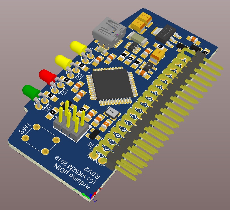
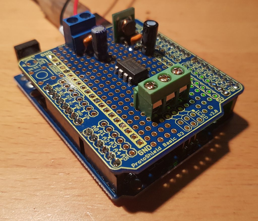
This new Arduino project monitors the voltage and current in a few external supply rails. Which can then be read by another device over the I2C. I’m sure at some point you’ll find the project code sitting in a public repository along with some hardware files as I complete and test a bit more of the project.
The bus pirates are great if you need to drive and interact with I2C devices. It implements a very simple macro style interface which means you can also edge case test and send out of order I2C signals to make sure your code is working.
So the first surprise with the new v4 unit was when I plugged it into my Windows 7 Dev machine, it needed a driver. I found it here here in the bus pirate archive (click), it actually wasn’t that easy to find. Once I’d updated the “driver” Win 7 it then did its usual thing and turned into a Serial Port.
Connecting to the Bus Pirate with PuTTY is relatively straight forward once you’ve found the serial port number, serial speed is 115200. It was then time to connect the wires. Dangerous Prototypes have a great page on how to do this, you can find it here (click). In a nutshell on my v4 board MOSI connected to SDA, CLK to SCK and GND to GND. Now back to the console. Firstly we need to get the Bus Pirate into I2C mode, so I used the following commands;
HiZ>m
1. HiZ
2. 1-WIRE
3. I2C
4. SPI
5. 2WIRE
6. 3WIRE
7. LCD
8. DIO
x. exit(without change)
(1)>3

I2C mode:
 1. Software
 2. Hardware
(1)>1

Set speed:
 1. ~5KHz
 2. ~50KHz
 3. ~100KHz
 4. ~400KHz
(1)>2
Ready
I2C>
As you will see I decided to select I2C software mode and a speed of 50kHz to start with. So now we need to turn on the power supplies and turn on the pull-up resistors to talk to the Arduino.
I2C>W
Power supplies ON
I2C>P
Pull-up resistors ON
Warning: no voltage on Vpullup pin
I2C>
Umm… hold the boat ! What’s happened to the pull-ups? That one threw me for a bit, I don’t remember the Sparkfun v3.6 units doing this.
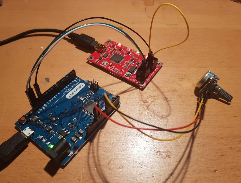
Well if you’ve only skim read the Dangerous Prototypes v4 page like I had you would have missed you need to connect the Vpu pin to one of the internal supplies, so in my case I used another wire to short Vpu to the 3V3 pin, conveniently they were adjacent to each other.
If you look closely you can see a yellow wire in the top right of the image above, that joins Vpu to 3V3 and is the secret sauce to making this work. Ok so now that’s solved I could then try to get the power supplies and pull-ups working again;
I2C>W
Power supplies ON
I2C>P
Pull-up resistors ON
I2C>
From here it was straight forward to the rest of the testing. Another good tid bit is the following macro is great for checking things work as expected, essentially it scans the bus and will report all of the devices it can talk to;
I2C>(1)
Searching I2C address space. Found devices at:
0x40(0x20 W) 0x41(0x20 R)
I2C>
Sweet. The Bus Pirate found my device and tells me I can read and write to it. More importantly I know what address to use, sometimes things get a little screwy due to the 7-bit I2C address and the read-write bit. Dangerous Prototypes have a good guide that allow you to work out what macros you need to use to build your I2C commands (click).
Here’s an example of me reading a single register from a specific address from within my Arduino I2C firmware;
I2C>[0x40 0x50[0x41 r]
I2C START BIT
WRITE: 0x40 ACK
WRITE: 0x50 ACK
I2C START BIT
WRITE: 0x41 ACK
READ: 0x08
NACK
I2C STOP BIT
I2C>
So the macro above can be read from left to right and in words;
- send a start condition
- the write address (0x40)
- a data byte (0x50)
- a second start condition
- the read address (0x41)
- read byte
- stop condition
.The bus pirate then prints that it READ a value of 0x08 from that register. Actually that value tells me there are 8 bytes in that register strucutre, so I can modify my macro and read the entire contents;
I2C>[0x40 0x50[0x41 r:8]
I2C START BIT
WRITE: 0x40 ACK
WRITE: 0x50 ACK
I2C START BIT
WRITE: 0x41 ACK
READ: 0x08 ACK 0x20 ACK 0x1C ACK 0x00 ACK 0x00 ACK 0x98 ACK 0x3A ACK 0x00                       NACK
I2C STOP BIT
I2C>
You’ll see that the last part of the above macro is now set to read 8 bytes and you can see the response from the unit appears to have data in it. The nice thing with an Arduino is you can have it print out messages on it’s serial port and then check the responses match, so I’m gong to call that working !
Now all I need to do is write a script that can then test all of the I2C edge cases to ensure my code really works and I’ll be able to move on to a more interesting part of the project.