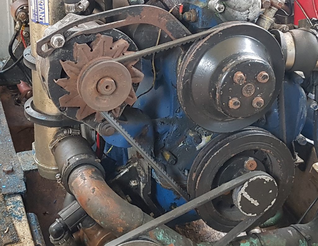
During the first sea trials of my Nereus at wide open throttle (WOT) it would slowly overheat with the coolant temperature rising from 85-ish degrees up over 100 degrees celcius. If I slowed down and dropped the revs the temperature would again slowly go back down. So either the cooling system was not quite able to pump enough raw water through the heat exchanger or the engine is producing too much heat. I certainly know that the heat exchanger is not blocked since it had been serviced recently.
When purchasing the boat the original owner had told us he’d changed the raw water impeller “a couple of years ago” so I’d purchased a spare impeller but not bothered to change it. The pump is right at the bottom of the engine in the bilge, so it’s a bit of a pain to get too which might also contribute to why it had not been changed.
Anyway I’d run the engine for about an hour on tap (towns) water but only at or just above idle, not under heavy load. So I decided to change the pump for peace of mind. A quick check on the internet and there was a YouTube video from 350vic that gave me some clues as to what was necessary, it didn’t look that hard.
Famous last words.
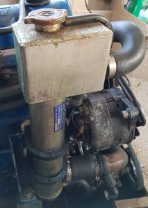
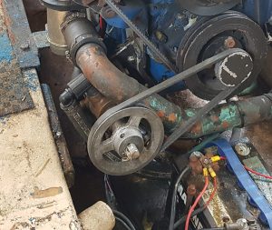
So first I had to get the pump out of the boat an supported by something that would make it easy to work on. Getting this pump out of the boat was as hard as I feared. There is not quite enough adjustment on the belt tension bolt to allow the belts to slip on and off the pulleys, in fact it hits the sump and if you’re not careful you can punch a hole in it. The bolts that support the lateral load of the pump and hold it in place you just can’t get a ring spanner on, so you have to feel for them using an open ended spanner and shift them a hairs breath, flip spanner, shift, flip spanner. If you’ve ever been forced to do this you will know how slow it is to back the bolt out just half a turn to loosen things off. With a few minor changes to bolt locations this could have been easily serviceable, oh well I do like a good project.
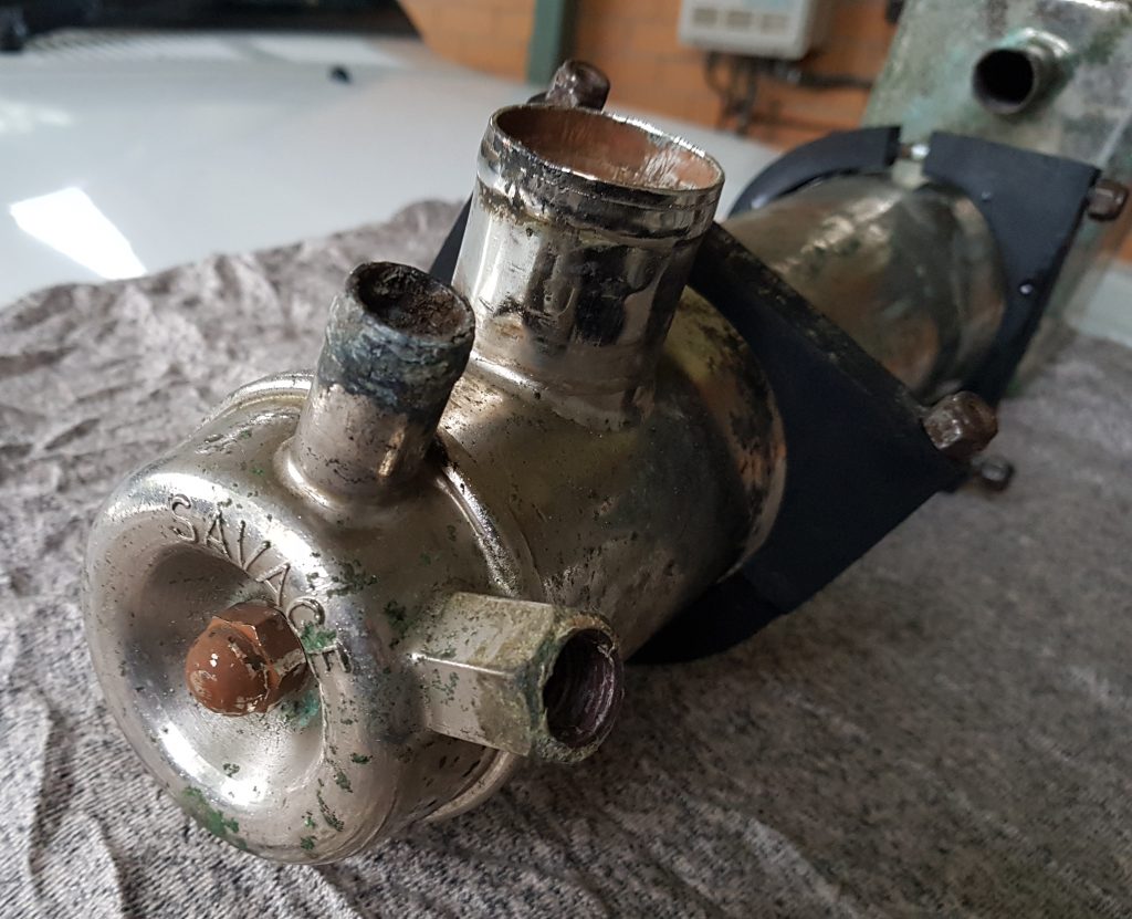
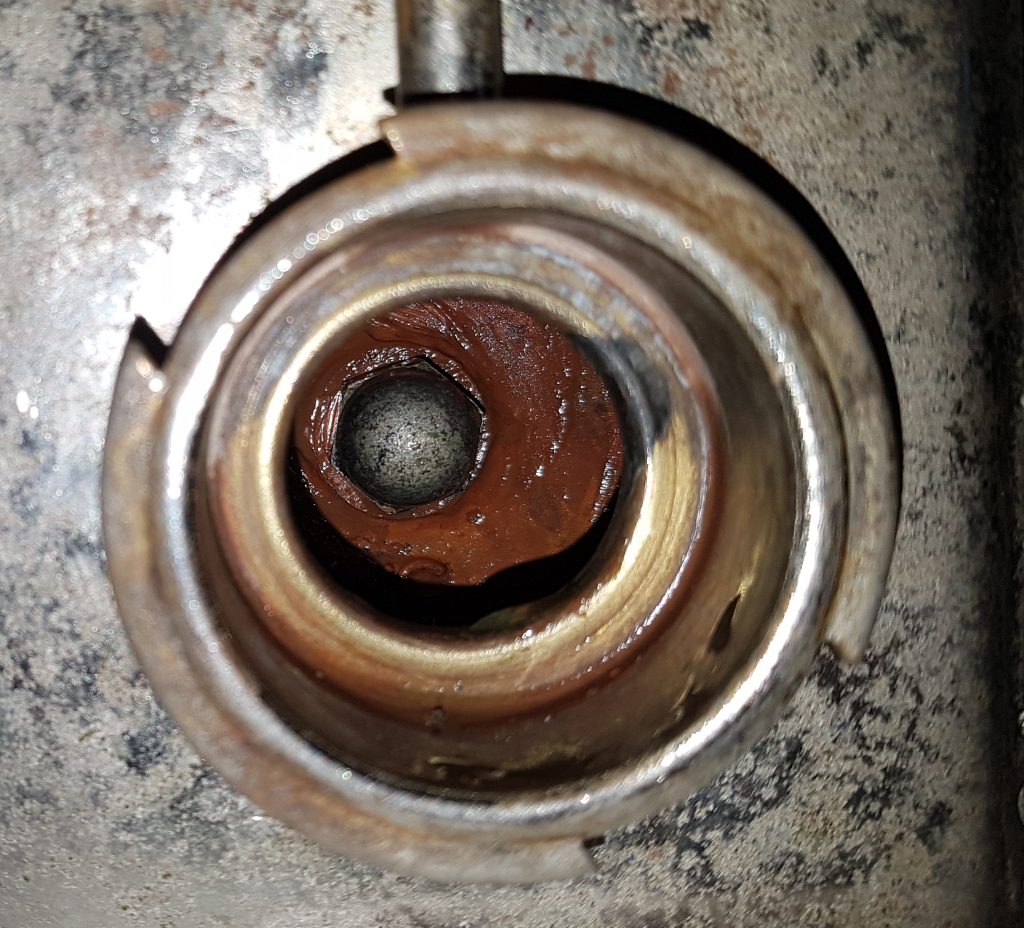
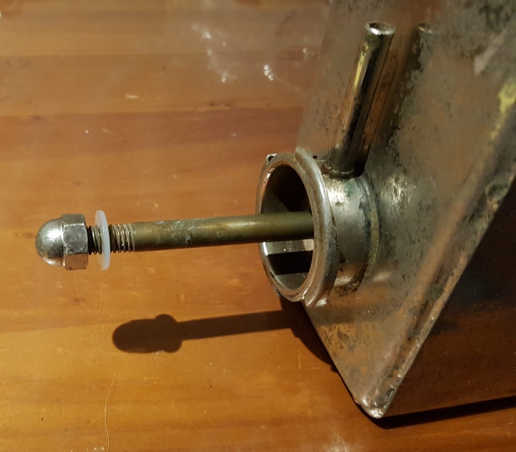
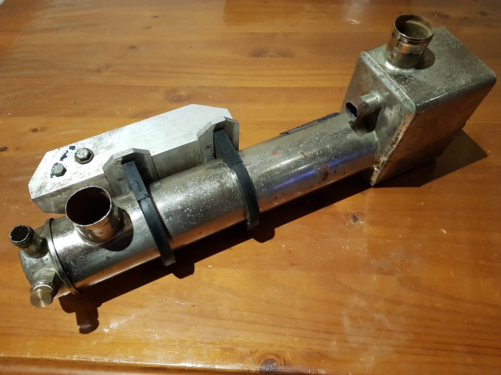
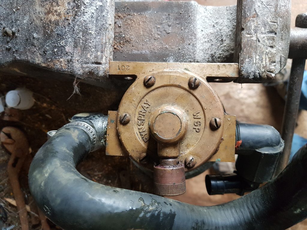
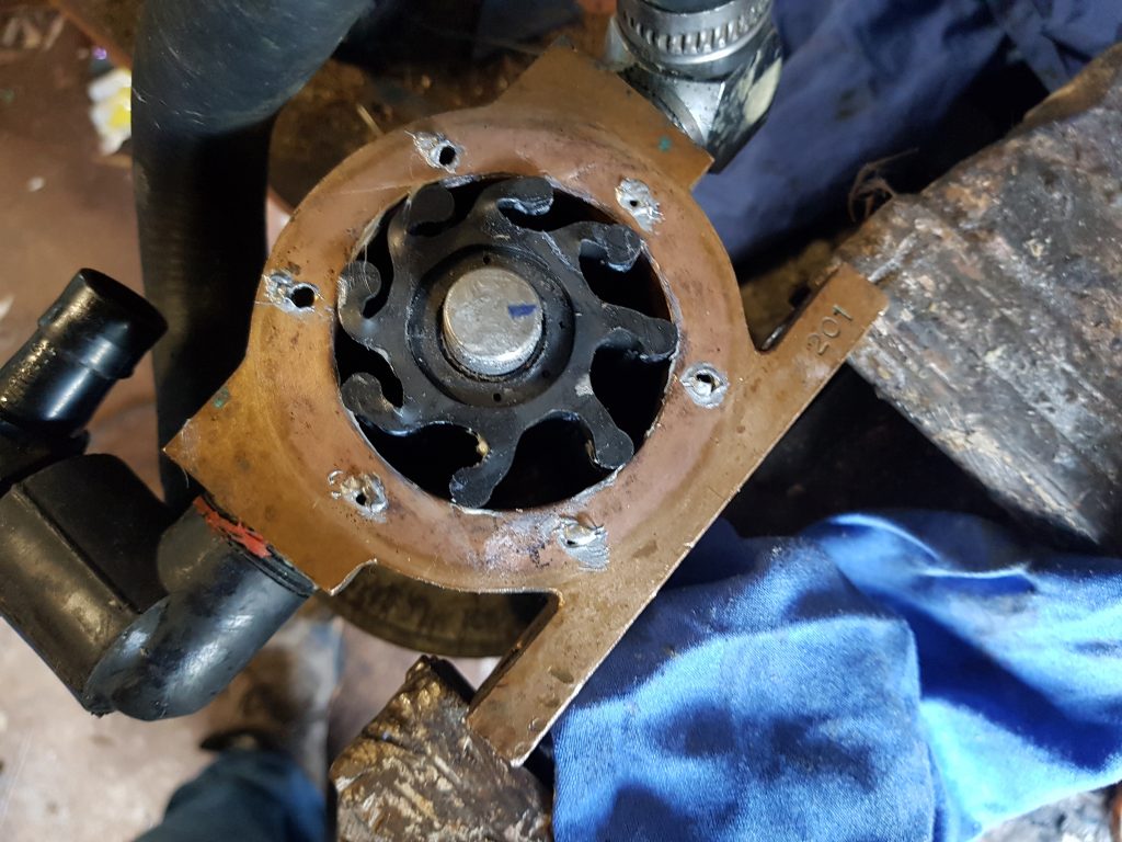
So after a good hour of extraction I managed to get the pump out an into a vice for support, here’s a series of shots that shows the pump being supported, the rear cover having been removed. The impeller didn’t look that bad, there’s a bit of wear on the rear of the vanes but there were no missing vanes and the pump wasn’t hard.
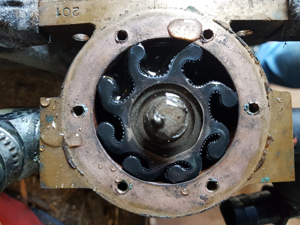
I’m not a fan of using the two screw drivers method for impeller extraction, bruising the face of the pump is just a no no. So for my first time I used vice grips and a slide hammer, being careful not to loose the bronze Woodroffe key. I will certainly be looking at a set of impeller pullers when I have some spare funds in the bank.
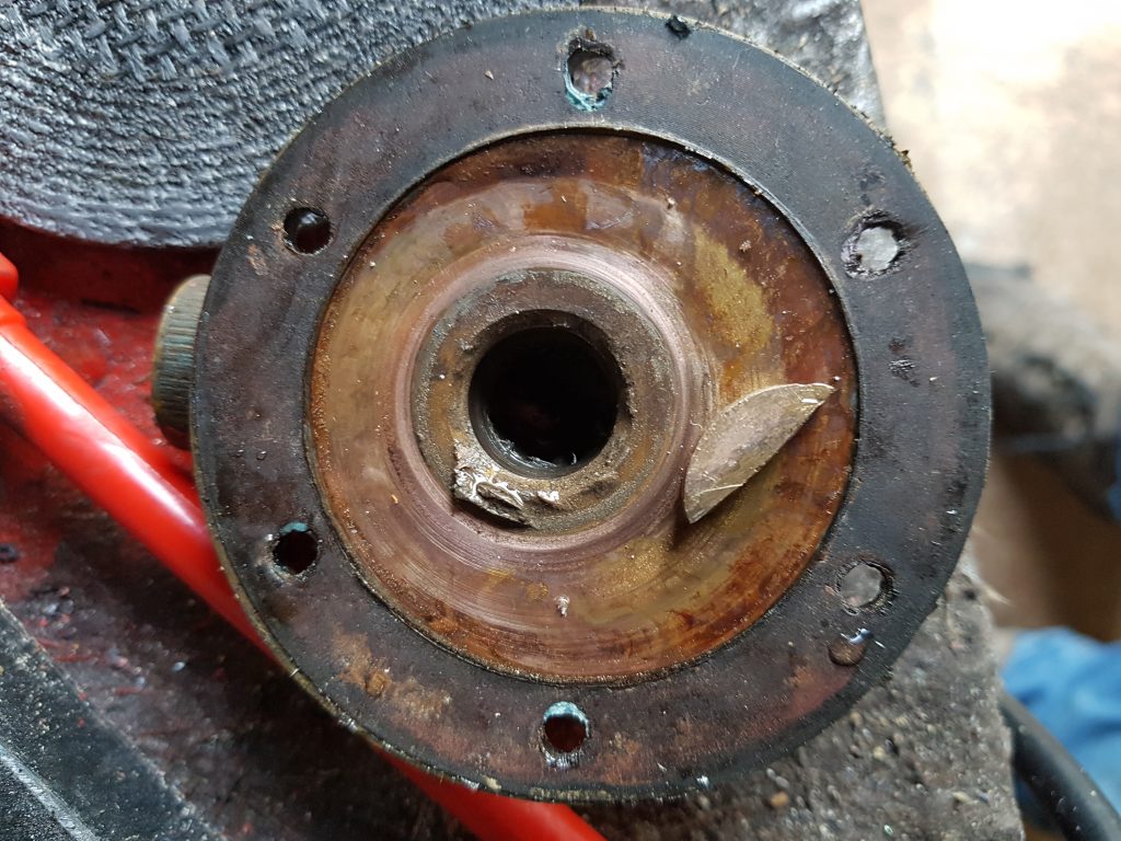
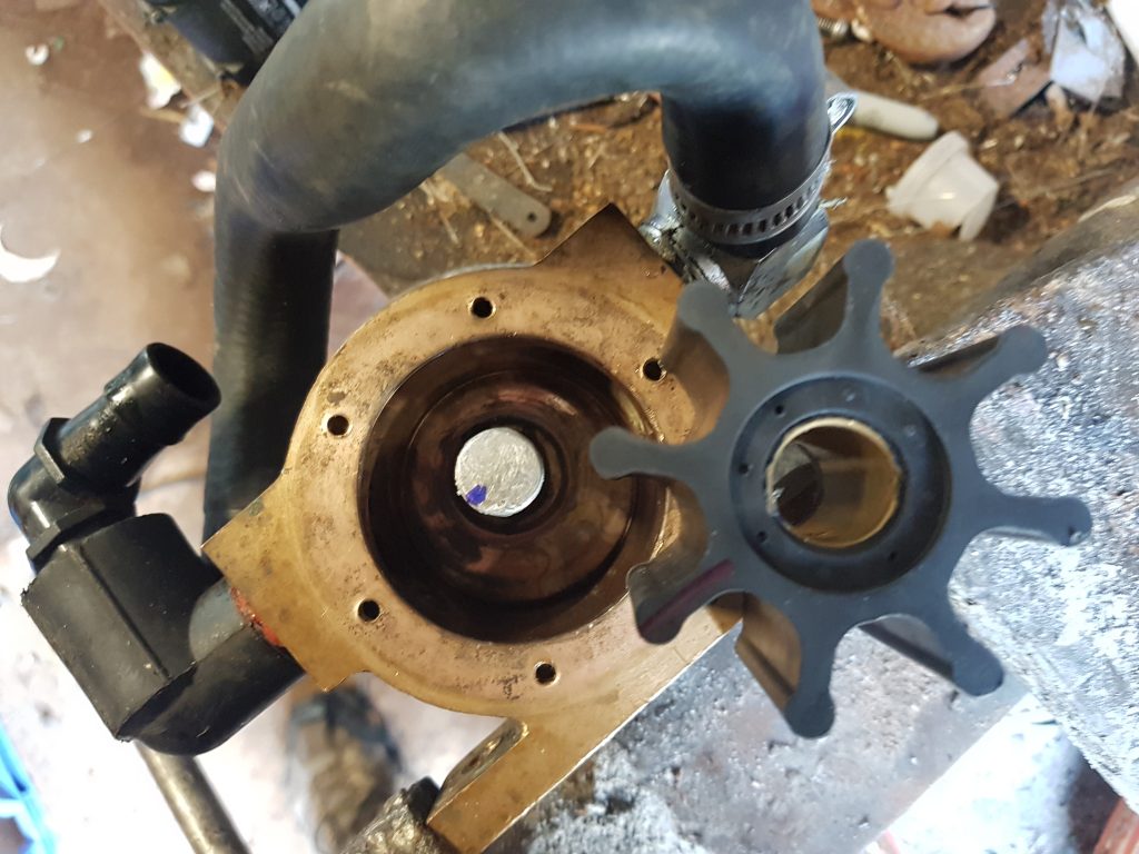
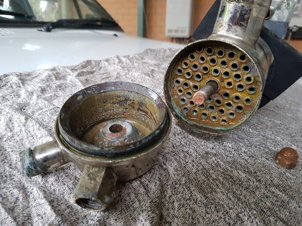
Above you can see the backing plate and Woodroffe key, along side the pump housing with the new impeller ready to go back in. So what they don’t tell you about re-assembling these pumps is you’ve got to bend the vanes of the new impeller, while inserting the impeller into the housing, which is offset to one side AND you need to catch the Woodroffe key in one movement. Oh and if you’re supporting the pump in a vice, then make sure the front of the pump is chocked otherwise everything tries to run away.
Needless to say it took me four attempts and a coffee after two to settle my frustration before I managed to get everything aligned and the pump re-assembled. After the first attempt I also marked the Woodroffe key location on the back of the shaft and the impeller so I had a chance of keeping them aligned. It certainly helped to dob a bit of grease on the back of the Woodroffe key and make sure the front edge was slightly down, but not too far down or it would then force the key down and lock it against the pump wall. Sigh.
To prevent the pump running dry I also lubricated the pump walls with a little marine clear grease, I see on some forums people use silicon spray or lanolin, YMMV.
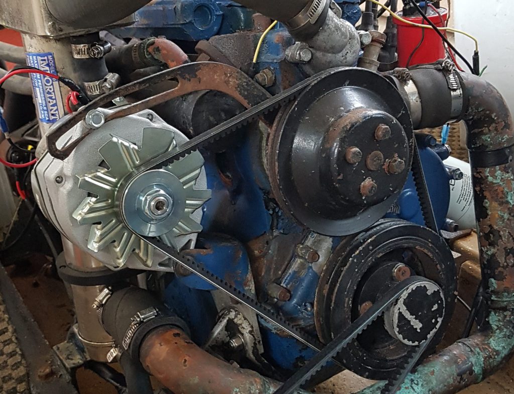
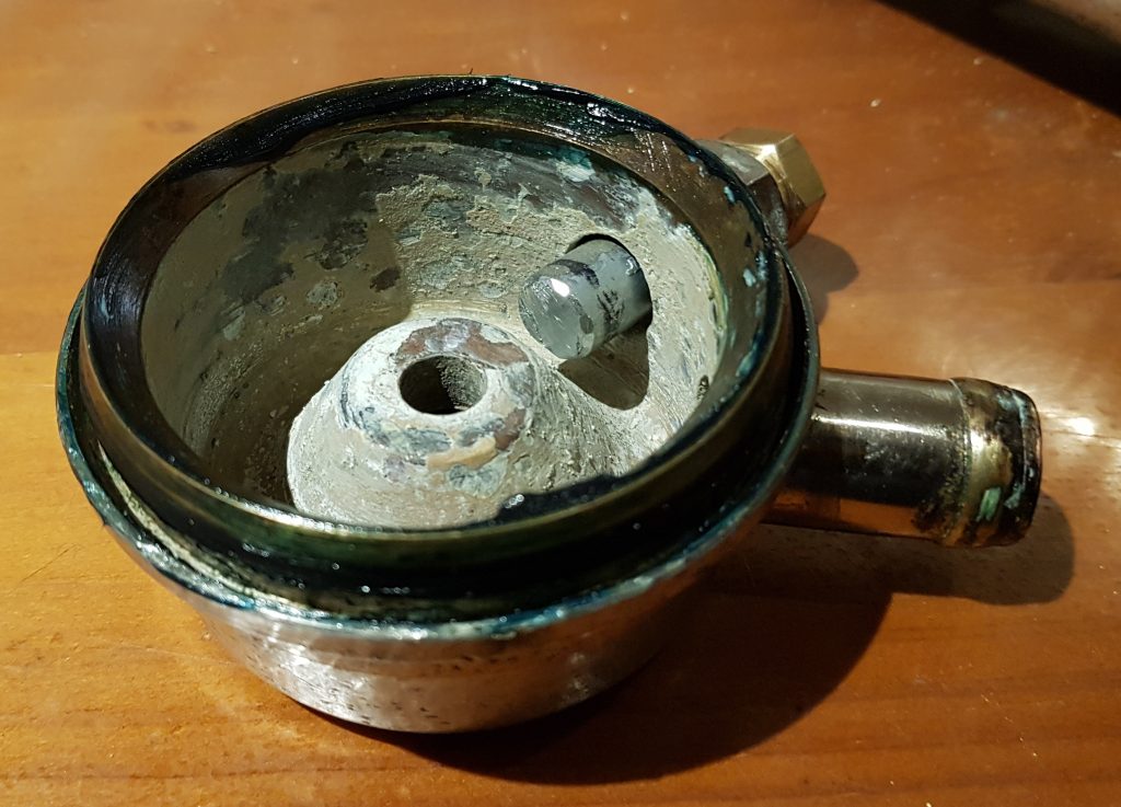
Hooray ! There’s the proof that I did get it back together and didn’t just go and buy a new pump out of frustration. I also dobbed a little “never seize” on the threads of the screws so it should come apart again in a year or so.
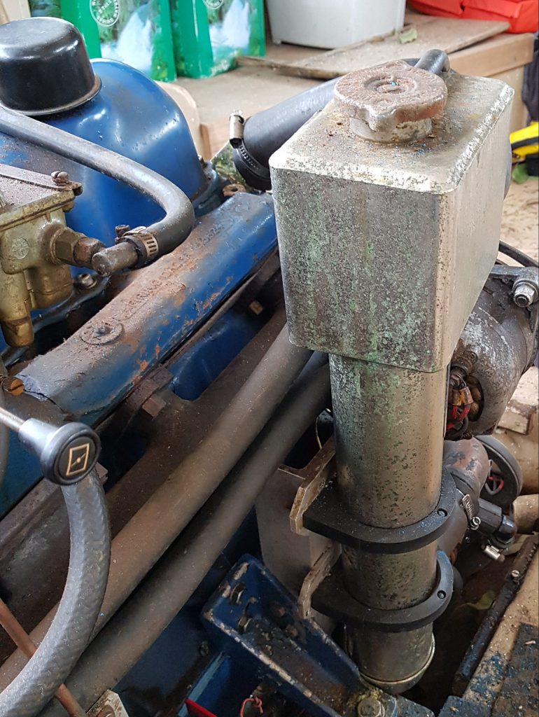
It was then just a matter of putting it back into the boat, reversing the disassembly process. Reminding me again why I need to replace the pump mounting assembly.